
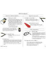
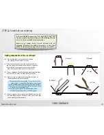
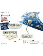

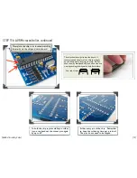
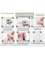


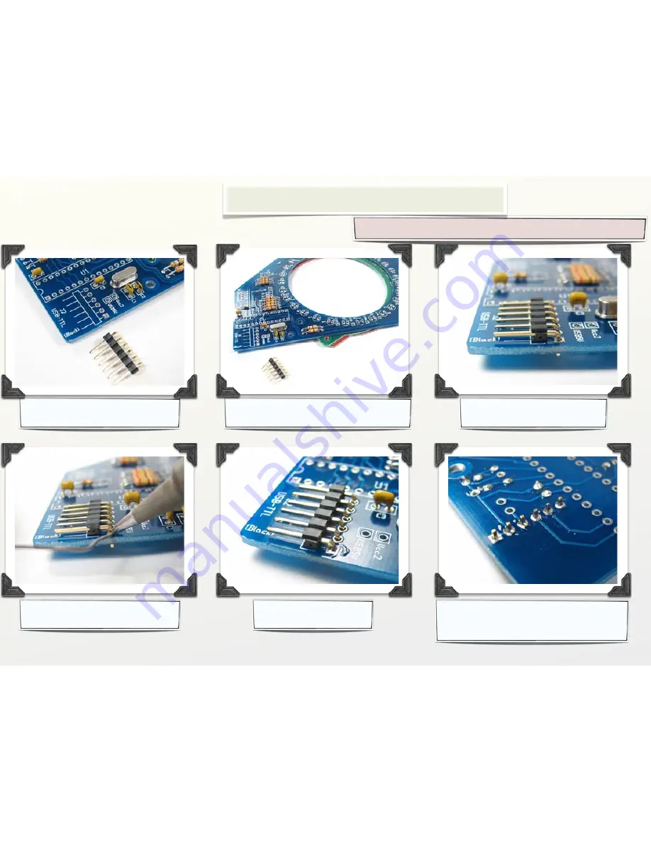
Part
#11
is a 6-pin header
that goes at location J2.
Set the circuit board atop the other two,
to raise it a bit above your work surface.
Place the header in its location;
it should sit flat as shown.
If you do not plan to connect to a computer, you can skip this step.
From the top, solder one pin of
the header to tack it in place.
Here’s how it looks with
one pin tacked in place.
Solder the other five pins on the bottom,
and then finish up the first one. The leads
do not need trimming.
[Bulbdial Assembly Guide]
[12]
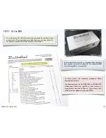
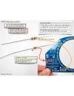
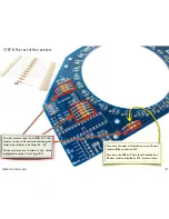
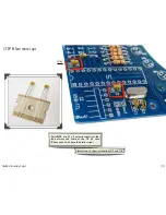
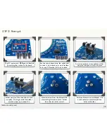
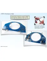
STEP 9: The USB-TTL connector
In this step, we add a header that allows the Bulbdial clock to
be connected to a computer through an FTDI USB-TTL cable.


