


[Bulbdial Assembly Guide]
[39]
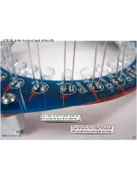
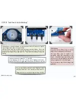
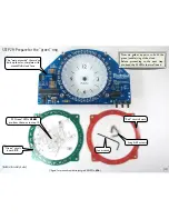
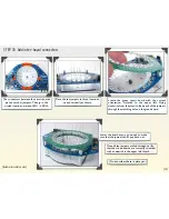
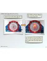
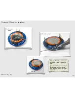
The connectors between the circuit boards
are ten zerohm jumpers. They go in the
circled locations, marked LED1 – LED10.
Place the ten jumpers in those locations,
on end vertically as shown.
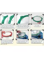
STEP 33: Add inter-board connectors
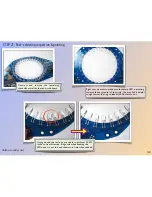
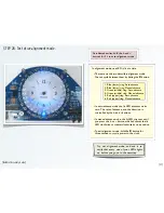
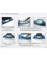
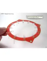
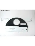
Locate the green circuit board with the correct
orientation–
!
Asterisk to the upper left. Going
clockwise from the asterisk, feed each of the jumpers
through the matching hole on the green board.
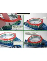
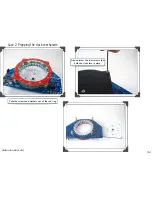
Lower the board as you go around to make
sure that the jumpers don’t pop back out.
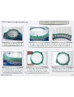
Once all ten jumpers are fed through, verify
that the circuit boards are correctly oriented–
with an asterisk in the upper left of each.
(Do not solder these in place yet.)


