background image

[64]

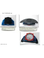
In alignment mode, one LED is lit at a time.  

Alignment mode

Hold the 

+

 and 

 buttons for 3 s to enter alignment mode.

• There are six sub-modes within alignment mode.

  You can cycle between them by hitting the 

Z

 button:

1.  Blue (lower) ring:  Auto advance

2.  Blue (lower) ring:  Manual advance

3.  Green (middle) ring:  Auto advance

4.  Green (middle) ring:  Manual advance

5.  Red (upper) ring:  Auto advance

6.  Red (upper) ring:  Manual advance

• In auto-advance mode, the lit LED advances on its
  own.  The rate of advance, and the direction, is

  controlled by the 

+

 and 

 buttons.

• To exit alignment mode, hold the 

Z

 button for 

  three seconds or cycle power to the clock.

• In manual advance mode, the lit LED stays put until 

  you press the 

+

 or 

 button, which advances the lit

  LED clockwise or counterclockwise by one position.

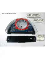
Optional configuration mode

Hold the 

+

 and 

Z

 buttons for 3 s to enter option mode.

• There are five sub-modes within alignment mode.

  You can cycle between them by hitting the 

Z

 button:

1. White balance:  Red Ring (upper ring) 

2. White balance:  Green Ring (middle ring)

3. White balance:  Blue Ring (lower ring)

4. Time Direction: CW/CCW

5. Fading:  On or Off

• The three “white balance” modes can be used for 
literal white balancing or for otherwise adjusting the 

relative brightness of the shadows.

  When entering one of these modes, the ring in 

question will circulate for a moment to indicate which 

ring is going to be adjustable.  After that, the time is 

displayed.   Each of the three components can be 

adjusted to 32 different levels (including off) by using 

the  

+

 or 

 buttons.  This can be used to turn off the 

second hand if desired.

• To exit  option  mode and  save  changes, hold  the 

Z


button for three seconds.

• Time direction allows the clock to be set to run 
counterclockwise, for rear-projection use.

• The fading option (default: on) specifies whether or 

not the clock fades between subsequent times 
displayed.

Alignment mode and optional configuration modes

[Bulbdial Guide]

Summary of Contents for Bulbdial

Page 1: ...se visit http wiki evilmadscience com Bulbdial The Bulbdial Clock kit is based on an original design concept by David Friedman of IronicSans com and developed at Evil Mad Scientist Laboratories The Bu...

Page 2: ...end hooks up to your USB port the other to the clock This allows you to program the Bulbdial Clock through the Arduino development environment http arduino cc Besides programming the cable can also b...

Page 3: ...s In the instructions we refer to components by their line item number on the bill of materials For example 14 is the ATmega168 microcontroller In some places the assembly procedure differs between ki...

Page 4: ...build we ll be placing various electronic components on the large blue circuit board In the second half we ll be building up and aligning the three rings of LEDs The rst ring is on the main board and...

Page 5: ...e Take one and bend it like so Now nd location JP1 Insert the jumper there and press it ush to the board Next Soldering STEP 3 Placing the first component Bulbdial Assembly Guide 5 Our rst component i...

Page 6: ...not so close that you re clipping the board itself Your tip needs to be shiny tinned If not melt some fresh solder against it and quickly swipe clean on a wet sponge Place the solder against the joint...

Page 7: ...ile we solder Flip the board over and get ready to solder Solder both pins to the board Inspect the solder joints make sure that they look shiny and wet Clip the excess leads short Bulbdial Assembly G...

Page 8: ...Assembly Guide 8 Now that we ve stepped through the basics we can proceed at a faster pace Resistors are added to the board in the same way as the zerohm jumper and are not sensitive to orientation P...

Page 9: ...e RGB kit There should already be a 68 ohm resistor installed at R10 as shown here STEP 6 The rest of the resistors The last resistor type is part 6 a 24 ohm resistor color code red yellow black gold...

Page 10: ...in place much like a resistor Parts 9 are 18 pF ceramic capacitors little yellow beads with two pins There are two similar types of ceramic capacitors in the kit so these ones are marked with a black...

Page 11: ...two of them at locations C3 and C6 Bulbdial Assembly Guide 11 STEP 8 Two more caps Parts 13 are 0 1 F ceramic capacitors that look almost the same as the 18 pF caps These ones don t have the black st...

Page 12: ...to a computer you can skip this step From the top solder one pin of the header to tack it in place Here s how it looks with one pin tacked in place Solder the other ve pins on the bottom and then nish...

Page 13: ...dial Assembly Guide 13 STEP 10 Buttons Parts 10 are right angle tactile button switches Snap them into locations S1 S2 and S3 and make sure that they sit at on the board Solder all four pins of each s...

Page 14: ...a AVR Microcontroller Part 14 is an ATmega168 a type of AVR microcontroller It goes in location U1 and must be oriented correctly First identify the end of both the chip and of location U1 that have t...

Page 15: ...gainst a hard at surface From end of chip YES no Bulbdial Assembly Guide 15 STEP 11b AVR Microcontroller continued Now place the chip in its location matching the marks on the chip and circuit board T...

Page 16: ...it is possible to solder one pin of the jack to tack it in place Solder one pin of the connector to tack it in place The larger metal here takes a while to heat up to about 8 s Here s the view from th...

Page 17: ...top of a pedestal such as the kit box If you do not plan to use an RTC module you can skip this step Solder one pin of each header to tack them in place Bulbdial Assembly Guide 17 STEP 13 RTC Sockets...

Page 18: ...t part of the build We now move on to putting the LEDs on board This is a 3D multi board circuit and we ll test each part individually as we go just to make sure that everything works in the end Bulbd...

Page 19: ...d the corner The LED bent with the guide with its 90 turn intact Your LEDs should look like this Executed properly the LED should have a sharp right angle bend and not spring out 19 STEP 14 The LED be...

Page 20: ...8 hex standoffs 18 Red circuit board 3 Before starting to put the rst ring of LEDs together gather up the necessary materials and have them at the ready You ll also need to bend the rst 30 LEDs to sha...

Page 21: ...mount the four long hex standoffs on the top side of the circuit board in the outer four holes Do not tighten the standoffs this is a temporary xture Tip If you press your nger your nger over the scre...

Page 22: ...s Bulbdial Assembly Guide 22 STEP 17 Insert first ring of LEDs Insert the LEDs one at a time into the pairs of regular holes on the back side facing inwards as shown Do not solder them yet Add all 30...

Page 23: ...ds of the LEDs Without ipping the assembly over feed a screw up through one of the corner holes Add the other hex standoffs the same way Once you have two on board the LEDs should be protected against...

Page 24: ...nter and in the same plane not wildly pointing up or down Finish adding the four short standoffs This loosely clamps the LEDs in place The four long standoffs can now be removed You may prefer to wait...

Page 25: ...the short leads of the LEDs 25 For each of the 30 LEDs solder the short lead the one at the rounded pad The reason that we re soldering just one pin is that we can use it as a hinge to adjust the LED...

Page 26: ...ing to identify LEDs that are not Bulbdial Assembly Guide STEP 21 Post soldering inspection pointing 26 Unscrew and remove the remaining standoffs as well as the red circuit board Going around the cir...

Page 27: ...der the remaining lead and then trim all the leads short on both pins Side Side The 100 uF capacitor if present is a small plastic covered cylinder Orientation matters The side of the capacitor is mar...

Page 28: ...spike 21 Hold the spike with your ngers while you tighten the screw with the hex wrench As usual be careful not to overtighten Thread four of the short M F standoffs into the four long standoffs thro...

Page 29: ...a power strip with a built in switch may be convenient for testing Bulbdial Assembly Guide STEP 24 Plug er in 29 Before we plug in the power supply check both sides of the board for stray debris espec...

Page 30: ...egular time display mode after a two second delay What you ll see looks like one LED slowly moving around and blinking This is the not yet aimed second hand of the clock and the blinking is to let you...

Page 31: ...l advance 3 Green middle ring Auto advance 4 Green middle ring Manual advance 5 Red upper ring Auto advance 6 Red upper ring Manual advance In auto advance mode the lit LED advances on its own The rat...

Page 32: ...a shadow of the gnomon Try not to touch other parts of the circuit board Ideally each shadow will look something like this However you should expect there to be variation and initially poor alignment...

Page 33: ...in both the brightness and viewing angle of LEDs Tiny variations in these can affect the spot size 3 This is only one ring Variation in LED position and angle will be less noticeable once all three ri...

Page 34: ...Bulbdial Assembly Guide 33 That wraps up the blue ring of LEDs In the next section we ll add the LEDs to the green ring using a similar set of procedures...

Page 35: ...standoffs clock face Hex wrench Long 4 40 screws Red circuit board 30 Green LEDs 16B pre form these as in step 14 Again for monochrome kits just grab 30 LEDs 16 Now we gather up parts to build the gr...

Page 36: ...gin inserting the LEDs into the pairs of holes on the bottom side much as we did on the main board Add all 30 LEDs Place the red ring on top of the lled ring As in step 18 place the bottom blank side...

Page 37: ...int the LEDs at the center of the ring This will improve centering of your shadows We now have the LED lled green ring clamped in place on top of the red one As in step 19 for each LED check that the...

Page 38: ...EP 32 Orienting the boards Soon will mount the boards together Before that we need to get their orientations correct The top side of each board has a secret asterisk star shape in the upper left corne...

Page 39: ...ors Locate the green circuit board with the correct orientation Asterisk to the upper left Going clockwise from the asterisk feed each of the jumpers through the matching hole on the green board Lower...

Page 40: ...the main board bend out the jumper leads so that they don t touch the clock face On the top side screw down the green board with the last four M F standoffs Solder the ten jumpers in place on the top...

Page 41: ...Bulbdial Assembly Guide 41 The green ring is now ready for testing Again check for stray debris on the circuit board before plugging it in...

Page 42: ...gnomon You may nd it helpful to look back at steps 26 28 for reference If any LEDs do not light at this stage it is likely to be a problem with soldering of a pin on the green board or on the jumpers...

Page 43: ...bdial Assembly Guide 43 STEP 36 Get ready to build the red ring As before use the LED bending guide to prepare 12 red LEDs 16C to go on the red circuit board Again for monochrome kits just grab 12 LED...

Page 44: ...Bulbdial Assembly Guide 44 STEP 37 Populate the red ring Hold the red ring with your ngers bottom blank side up Put the 12 LEDs into the holes...

Page 45: ...n just bend rather than clamp these LEDs into place Bend both leads out by about 45 The ring ready for soldering As in step 20 solder just the rounded pad of each LED Point each LED carefully towards...

Page 46: ...ed ring over the jumpers one at a time clockwise from the asterisk Like so Screw down the red circuit board using the nylon washers 26 as spacers Finally solder the ten jumper connections to the board...

Page 47: ...ain green boards The red ring is now ready for testing Again check for stray debris on the circuit board before plugging it in Use manual alignment mode to step through the LEDs one by one on the red...

Page 48: ...Bulbdial Assembly Guide 48 Your Bulbdial kit should now be ready to use Next we move onto the optional Chronodot module and case kit...

Page 49: ...real time clock battery backup module 4 pin SIL headers May be preinstalled Chronodot RTC module Important note Do not set the battery on any conductive surface or it will drain in a matter of minutes...

Page 50: ...tacles on Bulbdial PCB Place Chronodot on those headers note orientation With POWER OFF solder the 8 pins Next we ll need to add the battery Important note Placing the battery backwards can break the...

Page 51: ...battery Place battery as shown Solder the two tabs All done Note the Chronodot is active and powered as soon as the battery is added Again be careful not to rest the pins on conductive surfaces that c...

Page 52: ...Bulbdial Assembly Guide 52 Chronodot 4 Use it The clock must be restarted to detect the Chronodot If it is detected at startup the time displayed will not be 12 00 00 nor will it be blinking...

Page 53: ...Bulbdial Assembly Guide 53 Case 1 Here are the case parts One Arch Cover Two face plates One Base Cover...

Page 54: ...Bulbdial Assembly Guide 54 Case 2 Prepping the clock mechanism Take the screws and washers out of the red ring Also unscrew the four screws that hold the clock face in place...

Page 55: ...Bulbdial Assembly Guide 55 Most pieces have protective plastic lm on one or both sides Peel it off and discard Case 3 Peeling the dirt away...

Page 56: ...slits Check for debris in these holes and carefully push it out if you nd any The leads of a spare resistor work well The corresponding pieces of the thin cover plastic must be able to slip into the...

Page 57: ...n the back side of the clock assembly place but do not fasten the clock face where it goes Put one face plate over the back lining up the holes with the standoffs and the holes in the clock face Use t...

Page 58: ...iding shade for the clock face It is held in place by tabs at each end that index into the front and back faces The base cover is held in place by tabs in the middle that go into the faces plus tabs a...

Page 59: ...Bulbdial Assembly Guide 59 Case 7 Installing the case continued Base cover Insert left tab Insert middle tab Guide around buttons Insert right tab...

Page 60: ...washers over the holes Then we re ready to guide the front face on Watch all the tabs and take care not to bump the washers Neat trick To prevent the washers from sliding out while you install the fr...

Page 61: ...Bulbdial Assembly Guide 61 Case 9 Install front face plate screws As usual be careful not to over tighten the screws nger tight is tight enough...

Page 62: ...Bulbdial Assembly Guide 62 Case 10 Check arch cover Finally make sure that the arch cover has formed a nice arch between the front and back covers...

Page 63: ...levels The Z button the one closest to the edge of the clock toggles the LED display on and off It will still keep time while sleeping If you get stuck in any mysterious mode of the clock hold the Z...

Page 64: ...There are ve sub modes within alignment mode You can cycle between them by hitting the Z button 1 White balance Red Ring upper ring 2 White balance Green Ring middle ring 3 White balance Blue Ring lo...

Page 65: ...le to use the options to set all of the LEDs to be off all the time To avoid having a Bulbdial Brick you can restore your clock to defaults To restore defaults hold down the and buttons for 5 s after...

Page 66: ...e clock is likely to restart However you can use the computer to set the time on the Bulbdial clock The sync program is called SetArduinoClock pde and it s part of the Arduino DateTime library downloa...

Page 67: ...umper between locations Vcc2 and USB5V on the board Caution If you make this modi cation hooking up to a USB connector will provide power to the board So you must not hook up both the regular power su...

Page 68: ...the end Bulbdial Guide THE END If you liked this project you may find many others that you like at Evil Mad Scientist Laboratories www evilmadscientist com we invite you to visit and take a look arou...

Reviews: