background image


25


Note: Never leave the system filled with raw untreated water for any length of time. 
In order to guarantee the optimal performance of the unit check that the water quality is 
within BSRIA and CIBSE requirements and guidelines. 

SCALE BUILD UP AND CORROSION

 Topping up the circuit with non treated fresh water 

can produce: 

  Dissolved oxygen – Thus leading to potential corrosion 

  Carbonates: (produce scale build up): the water top ups must be reduced to 

the minimum.  

N.B: Scale and other residues may clog the heat meters within the ModuSat units, 
causing errors in the energy consumption calculations. 


WATER TREATMENT IS A STRICT REQUIREMENT AND MUST BE CHECKED IN THE 
FOLLOWING CASES: 

  Circuits with large capacity that produce large amounts of dissolved oxygen. 

  Frequent top ups due to leaks, repair and maintenance. 

  Use of water with characteristics that are not in line with the recommendations 

within this manual or in line with BSRIA / Evinox requirements. 


4.3 Precautions 

The correct operation of the unit, as well as the entire system, depends on good water 
quality. Water treatment is often an afterthought and consideration is not given to the 
amount of damage that can result from a poor cleaning and treatment regime.  

The warranty of the ModuSat storage unit is strictly related to the 
instructions and procedures indicated in this manual and the warranty does 
not cover any damage caused by scale and/or corrosion resulting from 
poor water quality.  

The components and materials used in the system assembly should also be checked to 
ensure they do not contribute to dissolved oxygen that can cause corrosion.  
Also:- 

  Ensure there are no depression pockets in the system 

  Remove gas permeable parts and materials 

  Ensure the expansion vessels are properly sized and the pre-charge pressure value in 

order to guarantee positive pressure, with respect to the ambient pressure, throughout 
the circuits.  

  Use suitable chemicals (such as BIONIBAL available from Evinox), which are suitable 

for the materials and equipment used and that 

PREVENT/INHIBIT CORROSION


Please note: If the completed installation includes boiler plant supplied by Evinox, 
then only BIONIBAL, which is approved by Evinox, should be used in the primary 
and secondary circuits.


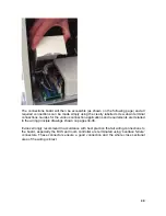
Our technical personnel, who will visit the project during the course of the 
installation and at its completion to arrange for its final commissioning and 
calibration, do so to assist the contractor and install team. This is to deal with any 

questions and queries; they do not perform the role of quality control or inspector of the 
installation or provide approval for the works carried out. The systems compliance with the 
consultant’s requirements and current standards and legislation remains the exclusive 
responsibility of the installer / M&E contractor and comments provided by Evinox are for 
guidance & advice only. 

Summary of Contents for ModuSat TP 40-10

Page 1: ...ModuSat TP Twin Plate Satellite Heating Unit Installation Commissioning and Servicing Instructions Evinox Ltd T 44 0 1372 722277 E technical evinox co uk W www evinox co uk 2551390A...

Page 2: ...raulic Connections 17 3 5 Use of Pre installation Rig 18 3 6 Wall Fixing 19 3 7 Pressure Independent Control Valve PICV Adjustment 21 4 PRIMARY AND SECONDARY CIRCUIT 24 4 1 Water treatment 24 4 2 Clea...

Page 3: ...h 3rd Party Room Stat 36 6 COMMISSIONING 37 6 1 Initial Commissioning Procedure 37 6 2 Apartment Circuit Balancing 38 6 3 Use of the commissioning switch 39 6 4 Adjustment of TMV 40 6 5 Pump Start up...

Page 4: ...alidate the warranty and absolves Evinox from any liability Evinox has the right to make any changes or modifications to the products without prior notice 1 2 Symbols Follows a list of symbols used in...

Page 5: ...5 ModuSat TP Top Connections...

Page 6: ...rcuit Side 1 Insulated plate heat exchanger Heating 2 Heating Pressure Independent Control Valve with actuator 3 Insulated plate heat exchanger Domestic Hot Water 4 DHW Pressure Independent Control Va...

Page 7: ...drain CW cold water HW domestic hot water TL1 TL2 T1 T2 T3 T4 T5 T6 T7 T1 T2 T3 T4 T5 T6 T7 PF PR CW HW SF SR PF PR CW SF SR DR HW DR B1 B2 B3 B4 B5 B6 B7 B1 B2 B3 B4 B5 B6 B7 TL3 TL4 T1 T2 T3 T4 T5...

Page 8: ...B4 B5 B6 B7 B1 B2 B3 B4 B5 B6 B7 BL1 BL2 T1 T2 T3 T4 T5 T6 T7 T1 T2 T3 T4 T5 T6 T7 CW HW CW PF PR DR SF SR PF PR HW DR SF SR B1 B2 B3 B4 B5 B6 B7 B1 B2 B3 B4 B5 B6 B7 BL3 BL4 T1 T2 T3 T4 T5 T6 T7 T1...

Page 9: ...2 T3 T4 T5 T6 T7 CW HW SF SR CW SF SR PF PR DR PF PR HW DR B1 B2 B3 B4 B5 B6 B7 B1 B2 B3 B4 B5 B6 B7 BL7 BL8 T1 T2 T3 T4 T5 T6 T7 T1 T2 T3 T4 T5 T6 T7 HW SF SR PF PR PF PR CW DR CW HW DR SF SR B1 B2 B...

Page 10: ...om Connections Note For clarity safety drain connections are not shown Please refer to hydraulic arrangements Additional connection configurations available as detailed on pages 7 9 of this manual For...

Page 11: ...t the Bottom Note For clarity safety drain connections are not shown Please refer to hydraulic arrangements Additional connection configurations available as detailed on pages 7 9 of this manual For s...

Page 12: ...nnections at the Bottom Note For clarity safety drain connections are not shown Please refer to hydraulic arrangements Additional connection configurations available as detailed on pages 7 9 of this m...

Page 13: ...own Please refer to hydraulic arrangements Additional connection configurations available as detailed on pages 7 9 of this manual For specific hydraulic arrangements for other connection configuration...

Page 14: ...ar Standard 16 Bar Optional Apartment heating circuit recommended cold fill pressure 1 5 bar DHW max static pressure 4 bar DCW min static pressure 0 5 bar Max supply temperature Primary 90 C Min suppl...

Page 15: ...onnections are kept in place to prevent ingress of any debris Take care when lifting this appliance and ensure your back is kept straight at all times Avoid twisting at the waist reposition the feet i...

Page 16: ...h connection to protect against possible electric shocks in line with current electrical regulations All electrical wiring should be installed checked by qualified personnel in line with current regul...

Page 17: ...undish that allows a visual check in the event of a system issue or valve discharge This must be installed in such a way so as to prevent damage or risk of injury to occupants children or animals Evin...

Page 18: ...he ModuSat TP Pre Installation Rig on the bracket STEP2 Fit the Evinox Flushing Bypass Valve Kit to the rig and then make final connections to the pipework running to the HIU STEP3 Shut off isolation...

Page 19: ...Sat TP is designed for wall mounting using brackets to be screwed to the wall as shown below 33 5 60 60 60 120 60 427 11 144 5 144 5 166 143 42 5 710 Please note Weights of the units are shown in the...

Page 20: ...ll that the ModuSat is being fixed to must be suitable for bearing the unit weight Where the wall is not load bearing an optional support frame is available on request The details of this frame are as...

Page 21: ...bar 2500 kPa 25 bar Connections Rp 3 4 F EN10226 1 Rp 3 4 F EN10226 1 Rc EN10226 1 91L 91H 93L 1 ModuSat TP HEATING 40 50 60 10 ModuSat TP 40 50 10 DHW ModuSat TP 60 10 DHW PRE SETTING Flow l h Flow l...

Page 22: ...ses by an Evinox engineer to ensure they are within the max min tolerance the following data can be checked For 91L ModuSat TP 40 10 50 10 60 10 HEATING For 91H ModuSat TP 40 10 50 10 DHW Please note...

Page 23: ...23 For 93L 1 ModuSat TP 60 10 DHW P1 H pressure port P2 L pressure port P1 P2 Q CONST Q CONST 25 kPa P1 P2 Q START UP PRESSURE If P1 P2 25 kPa THEN THE VALVE IS WITHIN THE WORKING RANGE...

Page 24: ...n mg litre Recommended levels are under 1 mg l Total iron this measures iron concentration in mg litre Recommended levels are under 1 mg l 4 2 Cleaning The cleaning and treatment of the systems must b...

Page 25: ...this manual and the warranty does not cover any damage caused by scale and or corrosion resulting from poor water quality The components and materials used in the system assembly should also be check...

Page 26: ...o discard any installation residuals if necessary clean it with an appropriate product and make sure that the circuit is well rinsed Once the circuit is well cleaned fill it with water again and add B...

Page 27: ...sition and bypass is open Turn screw in horizontal position for flushing of primary system Unit in normal operation Open to primary system Isolation valves are opened Handles in vertical position and...

Page 28: ...re and connect it to the relevant earth connection Important The connection to the electric power supply must be via a switched double pole fused connection fitted with a 3 Amp fuse to BS1632 Extensio...

Page 29: ...ed within the modusat itself under a removable metal cover To access the wiring board the full front case cover should be removed The connections board will be to your left as shown to take off the co...

Page 30: ...arious connection applications and requirements are detailed in the wiring principle drawings shown on pages 34 36 Evinox strongly recommend in accordance with best practice that all wiring connection...

Page 31: ...Connection Board Visible once the cover is removed Please Note When connecting external valves or pumps to the control board of the ModuSat it must be ensured that each connection does not exceed 1am...

Page 32: ...he ModuSat please refer to the electrical diagram using a 4x0 35 mm2 screened cable The cable must not be installed adjacent to other 220 240 Volt AC lines The ModuSat room controller s power is suppl...

Page 33: ...33 Once the tab has been released the cover can be hinged up to access connection Connection terminal with room controller 4 x 0 35 sqmm sheild...

Page 34: ...5 4 Typical ModuSat Electric Wiring Diagram Single Room Controller Note 3 Pumps valves must have localized power supply Switched neutral connection to be fitted with 1 amp in line fuse on neutral cab...

Page 35: ...ical ModuSat Electric Wiring Diagram with 2 Zone Control 2 Room Controllers Note 3 Pumps valves must have localized power supply Switched neutral connection to be fitted with 1 amp in line fuse on neu...

Page 36: ...36 5 6 Typical Wiring Diagram with 3rd Party Room Stat Note 3 Pumps valves must have localized power supply Switched neutral connection to be fitted with 1 amp in line fuse on neutral cable...

Page 37: ...ping the bypass valve fully open then opening the primary flow and return valves followed by the closing of the bypass is adhered to as previously described This prevents the components being exposed...

Page 38: ...comments provided by Evinox are for guidance advice only Once the initial commissioning checks have satisfactorily been carried out and checking the operation of both the heating and hot water functio...

Page 39: ...and held in for approximately 30 seconds The heating PICV opens and the pump starts its self venting procedure As described in section 6 5 The unit will then run at a pre set output temperature of 45...

Page 40: ...ed within 15 seconds and the mixed water temp is approximately 55 C 2 C The default valve setting is 55 C if this needs adjustment this can be done by loosening the top screw and turning the dial to t...

Page 41: ...after the initial first start up of the unit the Pump runs alternately with high and low speeds to help remove any air from the pump The pump should be left to carry out this process and once complete...

Page 42: ...ons and objects caused by Transportation Installation in which the Standards in force and good practice were not complied with Improper use of the device abnormal use conditions tampering by unauthori...

Page 43: ...able until passed as faulty by Evinox when a credit will be provided Any parts that have failed as a result of poor servicing or misuse will not be covered by our warranty Any modifications to the app...

Page 44: ...nstant preoccupation with an improvement of our materials any modification considered to be useful by our engineering departments and commercial can intervene without notice See full terms and conditi...

Page 45: ...td T 44 0 1372 722277 E technical evinox co uk W www evinox co uk Evinox reserves the right to make changes and improvements which may necessitate alteration to the specification without prior notice...

Reviews: