background image

Summary of Contents for Bobcat E251C

Page 1: ...25 HORSEPOWER MODELS E251C E251M 32 HORSEPOWER MODEL E251 HP 743 10 70 PART NO_ 261888 LlTHO U S A OUTBOARD MARINE CORPORATION 1970 ALL RIGHTS RESERVE D...

Page 2: ...USE AN APPROPRIATE CONTAINER FOR MIXING AND STORING THE FUEL To prepare the snowmobile fuel properly pour into aSEPARATE clean container half the amount of gasoline required and add all the required l...

Page 3: ...SPECIFICATIONS GENERAL SNOWMOBILE INFORMATION TROUBLE SHOOTING TUNE UP PROCEOURES FUEL SYSTEM IGNiTrON AND ELECTRICAL SYSTEM MANUAL STARTER ENGINE __ O_R_IV_E_T_R_A_IN __________________ STEERING TRAC...

Page 4: ...as a ready reference book for the experienced serviceman but will also provide more basic information for the guidance of the less ex perienced man The Parts Catalogs contain complete listings of the...

Page 5: ...the serviceman to give better service to the snow machine owner and thereby build or maintain areputation for reliable service This service manual covers all phases of servlcmg the 1971 snow mobiles...

Page 6: ......

Page 7: ...c SECTION 2 SPECIFICATIONS TABLE OF CONTENTS SPECIFICATIONS 2 2 TORQUE SPECIFICATIONS 2 3 2 1...

Page 8: ...urethane foam cushion Hood Molded fiberglass with built in headlights Lighting 2 Headlights and taillight Fuel tank 6 U S gallons Fuel Model 251 good grade regular Model 251 HP good grade premium Lub...

Page 9: ...00 Nut Saddle to Spring 3 8 24 25 30 Spark Plug 20 20 1 2 Nut Throttle Control Cable 30 40 Nut Tie Rod 3 8 24 18 20 Screw Truck to Frame Cleated Track Models 3 8 16 25 30 Screw Truck to Frame Molded T...

Page 10: ......

Page 11: ...SECTION 3 GENERAL SNOWMOBILE INFORMATION TABLE OF CONTENTS TWO CYCLE ENGINE THEORY 3 2 CARBURETION 3 3 IGNITION 3 3 POWER FLOW 3 4 3 1...

Page 12: ...ives the piston downward see Figure 3 1 Toward the end of the downward stroke ports which lead from the cylinder to the exhaust system are uncovered The expanding exhaust gases flow into these ports r...

Page 13: ...ect proportion of fuel and air to the engine for these various conditions The carburetor is essentially a simple metering device Needle valves permit a precise amount of fuel to flow to the carburetor...

Page 14: ...aring between the halves of the primary sheave assembly see Figure 3 7 The primary sheave assembly halves are separated by a compression spring in the hub of the movable half of the sheave As the engi...

Page 15: ...4 1 SECTION 4 TROUBLE SHOOTING TABLE OF CONTENTS DESCRIPTION 4 2 COMPRESSION 4 2 SPARK PLUGS 4 3 TROUBLE SHOOTING PROCEDURES 4 4 TROUBLE SHOOTING GUIDE 4 7...

Page 16: ...f fuel and air in the cylinders before ignition and receive the force of the power after ignition For maximum compression the cylinder must be round and the piston and piston rings correctly fitted to...

Page 17: ...n the cylinder See Figure 4 l Spark plugs are made in a number of heat ranges to satisfy a variety of operating conditions The heat range of a spark plug refers to its ability to dissipate heat from i...

Page 18: ...ine improperly connected e Fuel line kinked or severely pinched f Engine not primed g Clogged fuel line or fuel pick up in tank h Clogged check valve i Carburetor adjustments too lean j High speed nee...

Page 19: ...uled 2 Poor acceleration low top rpm a Incorrect gas lubricant ratio 4 5 b Old fuel c Fuel hoses plugged or kinked d Fuel pick up restricted e Fuel pump faulty f Incorrect carburetor mixture adjustmen...

Page 20: ...l loose d Crankshaft end play excessive e Carbon in combustion chambers and exhaust ports or on pistons 4 f Worn or loose bearings pistons rods or wrist pins g Loose assemblies bolts or screws h Manua...

Page 21: ...Check ignition coil output voltage to spark plug Recommend use of Neon light spark plug tester Do not allow open spark in engine compartment area where fuel is present be cause of potential fire hazza...

Page 22: ...ignition primary Check spark plugs Check coil and condenser these sometimes break down when they become warm Check points and timing Run engine with air intake filter assembly off If carburetor blows...

Page 23: ...ck carburetor Check fuel in tanks Check for excessive dirt or water in fuel system Check fuel tank cap vent for blockage Check that fuel pump is op erating See Seetion 6 If engine dies out and will no...

Page 24: ...inspect spark plugs might still run well yet not attain fuH efficiency If plugs are fouled the con Pre ignition itself is usually I l dition is probably caused by caused by pre ignition Wrong spark pl...

Page 25: ...tension lead and terminal If you have not yet found Check back into Engine trouble Runs Rough Most ignition failures are 11 due to malfunctions found in primary system See Section 7 U See Seetion 7 I...

Page 26: ......

Page 27: ...2 FUEL SYSTEM 5 2 IGNITION SYSTEM 5 2 COMPRESSION 5 2 NEW VEHICLE DELIVERY 5 3 TUNE UP PROCEDURES 5 3 IGNITION TIMING ADJUSTMENT 5 4 COMPRESSION RELEASE VALVE ADJUSTMENT 5 4 CARBURETOR ADJUSTMENTS 5...

Page 28: ...eginning of the season and at every tune up Astale fuel mix ture may cause hard starting stalling and faulty operation An alter native to the removal of fuel at the end of the season is the use of OMC...

Page 29: ...mponents which affect engine power and performance can be di vided into three groups namely 1 items affecting compression 2 items affecting ignition 3 items affecting carburetion Any tune up procedure...

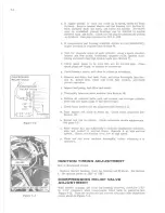
Page 30: ...6 Install tank refill with fresh fuel mixture and check primer operation i Inspect fuel pump fuel filter and hoses j Thoroughly lubricate snow machine see Section 12 k Tighten all external bolts nuts...

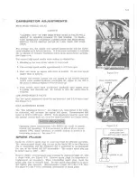
Page 31: ...open See Figure 5 5 IDLE ADJUSTMENT SCREW The Idie Adjustment Screw See Figure 5 5 when turned to the right or clockwise will increase the engine idle speed Recommended idle speed is 1100 to 1300 rpm...

Page 32: ......

Page 33: ...SCRIPTION 6 2 FUEL FLOW 6 2 CARBURETOR DISASSEMBLY CLEANING RE PAIR AND REASSEMBLY HD SERIES 6 2 LEAF VALVES 6 4 INSTALLATION 6 6 FUEL PUMP 6 6 REMOVAL 6 6 CLEANING INSPECTION AND REPAIR 6 6 REASSEMBL...

Page 34: ...HP ONLY FUEL RETURN UNE FUEL UNE CHECK VALVE MODEL 251 ONLY Figure 6 1 FILLER CAP 170 8 4 DISASSEMBLY CLEANING REPAIR AND REASSEMBLY HD SERIES The carburetor should be cleaned and inspected at regular...

Page 35: ...edle seato Assemble the insert into the cage with the molded rim side away from the inlet needle point Some HD carburetors are equipped with a rubber tipped needle a brass inlet seat and a copper gask...

Page 36: ...retor with compressed air Carefully blow out each channel and orifice in the casting k Assemble the carburetor Keep all parts clean before assembly to the body casting 1 Tighten the inlet seat to 40 5...

Page 37: ...DO NOT damage or interchange the leaves d The leaves must be flat to maintain a seal with the leaf valve body DO NOT under any circumstances bend or flex the leaves by hand 6 5 17 143 1 Carburetor Ga...

Page 38: ...uel pump and filter assembly see Figure 6 8 b Remove two screws attaching pump and filter assembly to mount ing plate see Figure 6 8 and remove pump and filter assembly NOTE Filter assembly may be rem...

Page 39: ...and break in instructions see Section 12 b The importance of using a fresh clean fuel mixture cannot be overstressed Gum will form in old fuel which will clog filter screens fuel passages carburetor o...

Page 40: ...I...

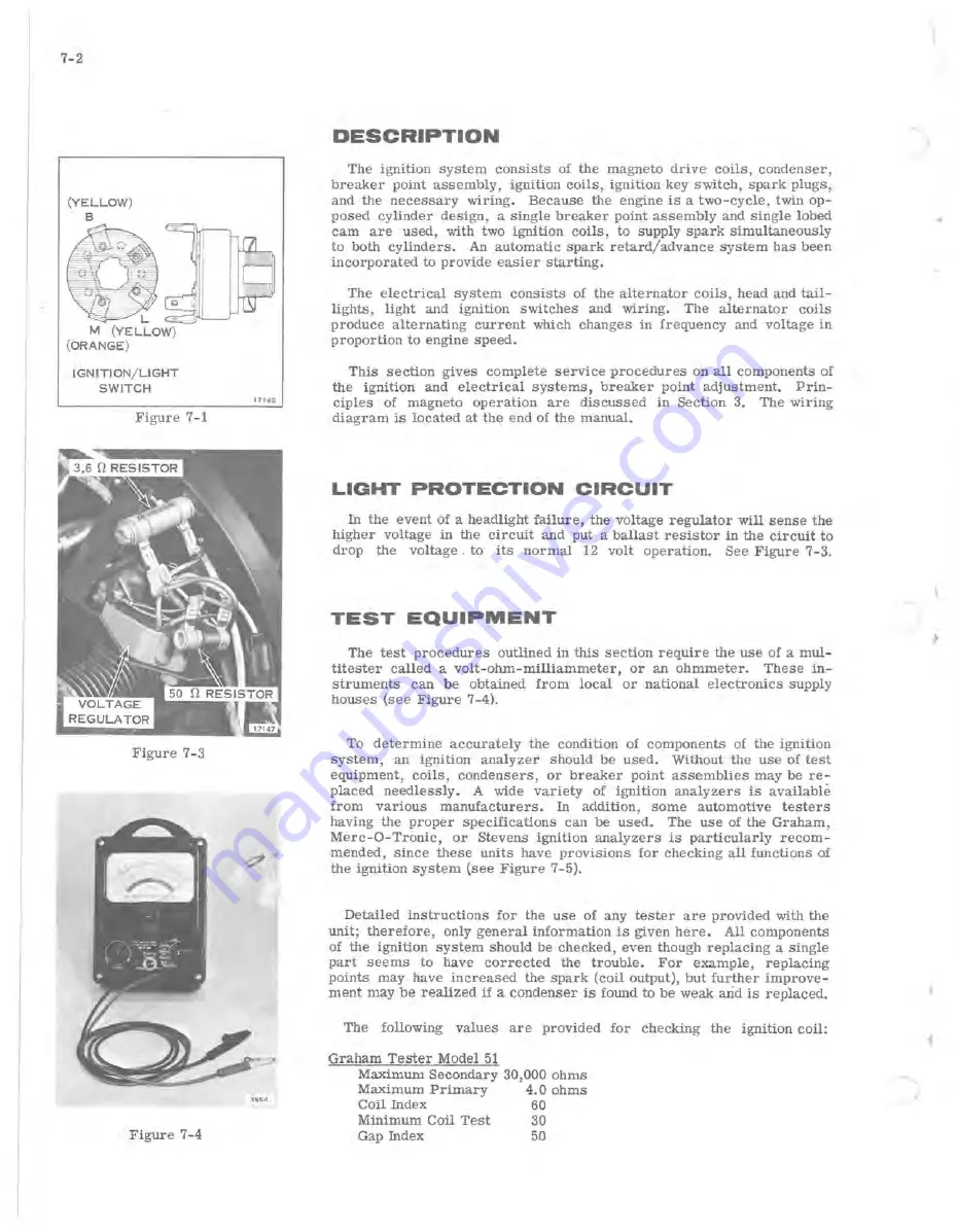
Page 41: ...SCRIPTION 7 2 LIGHT PROTECTION CIRCUIT 7 2 TEST EQUIPMENT 7 2 MAGNETO 7 5 REMOVAL 7 5 TESTING 7 5 FLYWHEEL 7 5 BREAKER POINTS 7 5 CONDENSER 7 6 MAGNETO DRIVE COILS 7 7 IGNITION COILS 7 7 HIGH TENSION...

Page 42: ...lt operation See Figure 7 3 TEST EQUIPMENT The test procedures outlined in this seetion require the use of a mul titester called a volt ohm milliammeter or an ohmmeter These in struments can be obtain...

Page 43: ...igure 7 9 using flywheel puller Service Tool 378103 Magneto drive coils condenser and breaker point assembly are now accessible for servicing see Figure 7 10 e Disconnect primary leads from terminals...

Page 44: ...quate screw engagement to hold breaker point gap of 022 024 Set points on highest point of cam lobe Breaker point spring tension is predetermined and does not require adjustment Dirt foreign particles...

Page 45: ...bosses on the magneto plate the gap between the flywheel magnet and coil heels may be too great Connections that are not clean and tight will cause high resistance which will limit current flow Visual...

Page 46: ...ge and with the breaker cam and key installed on the crankshaft see Figure 7 17 Point gap should be set to 022 024 inch with the breaker arm on the high lobe of the cam full open g Rotate crankshaft s...

Page 47: ...ixture or improperly installed spark plugs can cause overheating The condition of spark plugs may provide an indication of other con ditions requiring attention Inspect each plug and gasket as it is r...

Page 48: ...orque wrench Improper installation is one of the greatest single causes of unsatis factory spark plug performance Improper installation is the result of one or more of the fOllowing 1 Installation of...

Page 49: ...r 8 1 SECTION a MANUAL STARTER TABLE OF CONTENTS DESCRlPTION 8 2 REMOVAL AND DISASSEMBLY 8 2 CLEANING INSPECTION AND REPAIR 8 3 REASSEMBLY 8 3 STARTER ROPE RE PLACEMENT 8 4...

Page 50: ...EMBLV It is good practice to wear safety glasses while disassembling and reassembling manual starters a Remove four screws see Figure 8 1 attaching manual starter as sembly to fan housing Remove start...

Page 51: ...anchor hole lines up approx with starter rope hole in starter housing i Lock starter pulley in position by aligning holes in pulley and housing and inserting a nail or pin through them j Tie a knot in...

Page 52: ...r rope to length of 73 3 4 inches Fuse ends of rope over open flame for about one half inch Rope ends must be stiff to hold in pulley and rope anchor Tie knot in end of rope and thread through pulley...

Page 53: ...GASKET SURFACES 9 6 PISTONS 9 6 BEARINGS 9 7 ASSEMBLY OF ENGINE PISTONS WRIST PINS AND CONNECTING RODS PISTON RINGS CRANKSHAFT CYLINDERS INSTALLATION OF ENGINE ASSEMBLY TO CHASSIS 9 8 9 8 9 8 9 9 9 1...

Page 54: ...shown in Figure 9 2 Keep fingers from between halves of secondary sheave when performing next step Movable half of sheave is spring loaded and will snap elose when belt is removed c From left side of...

Page 55: ...move manual starter ratchet assembly flywheel magneto cam and inner fan housing See Seetions 7 8 e Remove compression relief valve f Remove spark plugs g Remove exhaust manifolds from cylinder barrels...

Page 56: ...from which they are removed k Remove connecting rod caps 1 Remove connecting rods from crankshaft m Reinstall matched caps on connecting rods n Remove rings from pistons DO NOT try to save the rings e...

Page 57: ...le Bearing Model 251 HP 9 Connecting Rod Cap 27 Rear Exhaust Manifold Model 251 10 Connecting Rod Screw 28 Muffler Clamp Model 251 Only 11 Cylinder Gasket 29 Gasket Model 251 Only 12 Front Cylinder 30...

Page 58: ...bly b Remove all traces of dried cement and old gasket material using trichlorethylene or lacquer thinner c Check gasket faces for flatness Under certain conditions gasket faces may warp or spring par...

Page 59: ...crankshaft by e mersing them in a cleaning solvent and turning outer race of bearing Flush all dirt from around balls and separators Tank should be equipped with a screened false bottom to prevent set...

Page 60: ...etc with clean oil before assembly NOTE Use new gaskets and seals throughout when reassembling the engine Apply Perfect Seal 4 to both sides of crankcase gasket before assembly PISTONS WRIST PINS AND...

Page 61: ...of the same rod be turned end for end Match marks are provided to assure correct assembly Draw a pencil over edge surface on both sides of rod to make certain that cap and rod are correctly aligned se...

Page 62: ...ase group to engine frame d Install compression relief cable assembly and adjust See Page 5 4 e Install inner fan housing with magneto and alternator flywheel and outer fan housing See Figure 9 10 f I...

Page 63: ...e putting vehicle in gear Start out slowly avoid jack rabbit starts DO NOT overspeed engine Op eration in extreme cold weather can cause a slow down in the drive and track mechanism When this occurs b...

Page 64: ...a1 inches so that 10wer muffler can be removed REASSEMBLV MODEL 251 1 Reassemble in reverse order first making sure mating surfaces are clean and smooth Use new asbestos tape in the exhaust pipe to mu...

Page 65: ...EMBLY 10 3 DRIVE CHAIN 10 4 LUBRICATION 10 4 ADJUSTMENT 10 4 REMOVAL 10 4 INSTALLATION 10 4 REPAIR 10 4 BRAKE 10 4 DESCRIPTION 10 4 ADJUSTMENT 10 5 REMOVAL 10 5 REPAIR 10 5 REASSEMBLY 10 5 FINAL ADJUS...

Page 66: ...y can be turned off the crankshaft DISASSEMBLY OF SHEAVE WHILE ON ENGINE 1 Remove belt see Section 9 2 Remove two screws securing lock plate to end cap assembly see Figure 10 2 Primary sheave is sprin...

Page 67: ...3 Place movable half of sheave on shaft compress spring and lock in place with strap Service Tool No 261906 4 Assemble end cap on shaft making sure end cap splines engage shaft splines 5 Before placin...

Page 68: ...measure the slack at this point If the chain requires adjustment use the following steps 1 Loosen adjusting screw lock nut see Figure 10 9 2 To tighten chain pivot the eccentric adjustment downward s...

Page 69: ...cks If the free floating puck 6 is one half of its original 1 2 thickness it should be replaced When the fixed puck 7 is worn so that there is only 1 32 protruding from the carrier 8 it should be repl...

Page 70: ...Actuate hand lever and set parking brake lock to check for proper adjustment c Release parking brake lock and check if the cable clamps retain cable in static position during brake operation d Tighten...

Page 71: ...13 Press cups 19 from eccentric CLEANING AND INSPECTION 1 Clean bearing in trichloroethylene see lIi_il on page 9 6 2 Check bearing for wear or roughness 3 Check shaft sheaves woodruff keys and Delri...

Page 72: ...eload spring by holding end cap stationary and rotating movable sheave clockwise to engage next ramp on end cap approximately 1 3 turn 19 Compress spring to allow installation of end cap retaining rin...

Page 73: ...2 REASSEMBLY 11 2 SKI ALIGNMENT 11 2 TRACK AND SUSPENSION 11 3 TRACK TENSION ADJUSTMENT 11 3 TRACK ALIGNMENT ADJUSTMENT 11 3 REMOVAL OF TRUCKS AND TRACK 11 4 FRONT AXLE DISASSEMBLY 11 4 REAR AXLE DIS...

Page 74: ...r damaged f Check for 1 16 end play in steering column Correct by moving steering column support REASSEMBLY a Reassemble skis to leaf springs b Replace ski column and assemble to steering arm Lubricat...

Page 75: ...ck nut on pivot arm adjusting screw See Figure 11 4 c Adjust track so that the distances shown in Figures 11 3 and 11 4 are obtained d Measure distance from front edge of adjusting bracket to anchor I...

Page 76: ...track tension locknuts See Figure 11 4 10 Rear axle can now be removed 11 Molded Track Only Remove idler assembly Remove nut and washer from each end ofaxle as in Step 3 See Figure 11 6 12 Trucks axl...

Page 77: ...ot hamper the operation of the snowmobile 3 Liquid neoprene can be applied to cracks or frays to help restore its original appearance Cleated Track If track is badly cut through and belts separated it...

Page 78: ...track or wheels molded track bear ings bearing retainer retaining ring pivot arms and brackets to rear axle Use a clean light oil to assist in this assembly Observe IIII_ l lII IIli l on Page 11 4 App...

Page 79: ...BLE OF CONTENTS ENGINE LUBRICATION 12 2 FUELS AND LUBRICANTS 12 2 OMC 2 4 FUEL CONDITIONER 12 2 FUEL BLENDING 12 3 LUBRICATION RECOMMENDATIONS 12 3 PREVENTIVE MAINTENANCE 12 4 STORAGE 12 5 PREPARATION...

Page 80: ...ine in the 251 HP The oil container should be marked Service MM or Service MS Additional markings such as ML MM DG or DS indicate oils for other applications and should be avoided Avoid the use of low...

Page 81: ...te the mixture A clean funnel equipped with a fine screen should be used when pouring the fuel mixture into the snowmobile tank Whenever it is necessary to mix fuel and lubricant at temperature below...

Page 82: ...or install new fuel pump filter screen FUEL FILTER Exercise care to prevent fuel spillage when removing fuel filter when engine is hot The fuel filter is attached to the fuel pump See Figure 12 4 To i...

Page 83: ...groWld to take weight off track and skis i Loosen track tension see Section 10 j Drain and clean fuel tank see Section 6 k Remove transmission belt l Rub bottom of skis primary and secondary drive sh...

Reviews: