background image

2

2.  Outdoor use advice

Figure 1 - Enclosure with walls on all sides but

no overhead cover.

Figure 2 - Partial Enclosure with overhead cover and

no more than two walls.

Figure 3 - Partial Enclosure with overhead cover and

no more than two walls.

This appliance shall only be used in an above ground open-air situation with natural ventilation, without stagnant areas, 

where gas leakage and products of combustion are rapidly dispersed by wind and natural convection.
Any enclosure in which the appliance is used shall comply with one of the following:

• 

An enclosure with walls on all sides, but at least one permanent opening at ground level and no overhead cover. See 

Figure 1.

• 

Within a partial enclosure that includes and overhead cover and no more than two walls. See Figure 2 & 3.

• 

Within a partial enclosure that includes an overhead cover and more than two, the following shall apply: 

-At least 25% of the total wall area is completely open; and 

-At least 30% of the remaining wall area is open and unrestricted. See Figure 4 & 5.

• 

In the case of balconies, at least 20% of the total side, back and front areas shall be and remain open and unrestricted.

The following diagrams provide a diagrammatic representation of outdoor areas. Rectangular areas have been used in these 

figures - the same principles apply to any other shaped area.
This appliance is not intended to be installed in or on boats, and is not intended to be installed in or on recreational vehicles.

Figure 4 - Open side at least 25% of total wall area.

30% or more in total of the remaining wall area is

open and unrestricted

Summary of Contents for AGA AGA-10-0096-LP-CE

Page 1: ...E FOR FUTURE REFERENCE Installations Operation Instructions CAUTION THIS UNIT IS HEAVY PROPER EQUIPMENT AND ADEQUATE MANPOWER MUST BE USED IN MOVING THE RANGE TO AVOID DAMAGE TO THE UNIT OR THE FLOOR REMEMBER when replacing a part on this appliance use only spare parts that you can be assured conform to the safety and performance specification that we require DO NOT use reconditioned or copy parts...

Page 2: ... completion of the repair we will return the product back to yourselves PLEASE NOTE The manufacturer s warranty is not transferable What is not covered by this warranty Conditions and damages resulting from any of the following Improper or inadequate installation delivery use storage or maintenance Any repair not authorised in writing by AGA Rangemaster Ltd any modifications misapplications or unr...

Page 3: ...III My AGA Details Model Nos AGA Professional Series Gas Grill 25G drop in AGA 10 0096 LP CE Serial No AGA Service No AGA Dealer or store contact No Date of Installation ...

Page 4: ...12 9 Assembling cook surface retaining fasteners 13 10 Installing cook surface 1 of 3 14 10 Installing cook surface 2 of 3 15 10 Installing cook surface 3 of 3 16 11 Gas Type Gas Pressure and Heat Inputs 17 12 Gas Connections 18 13 Gas Soundness 19 14 Gas burner and injectors 20 15 Final installation checks 20 16 Operating Instructions 21 17 25G Temperature Control 22 18 Lighting Instructions 23 1...

Page 5: ...fully follow all of the messages FOR YOUR SAFETY If You Smell Gas 1 Shut off gas to appliance 2 Extinguish any open flame 3 Remove grill cooking surface 4 If odour continues immediately call your gas supplier or your fire department FOR YOUR SAFETY 1 Do not store or use gasoline or other flammable vapours and liquids in the vicinity of this or any other appliance 2 An LP Tank not connected for use...

Page 6: ...ial enclosure that includes and overhead cover and no more than two walls See Figure 2 3 Within a partial enclosure that includes an overhead cover and more than two the following shall apply At least 25 of the total wall area is completely open and At least 30 of the remaining wall area is open and unrestricted See Figure 4 5 In the case of balconies at least 20 of the total side back and front a...

Page 7: ...OOKING SPILL OVERS AWAY FROM FRONT CONTROL PANEL AND ALL OPEN SERVICE AREAS NEVER HOSE UNIT OR SPRAY UNIT WITH PRESSURIZED CLEANING SOLUTIONS n CAUTION CAREFULLY FOLLOW ALL INSTALLATION INSTRUCTIONS AND CONSTRUCT ALL COUNTER SPACE STANDS OR OTHER SURFACES TO THE RECOMMENDED INSTALLATION SPECIFICATIONS AS OUTLINED IN THIS MANUAL n CAUTION THIS UNIT IS HEAVY AND SHOULD BE INSTALLED BY TWO PEOPLE USE...

Page 8: ...t and place next to installation area Take care not to scratch drip pan during installation Chassis Lift chassis from crating box and place on its side next to installation area Use caution since ignition components are exposed Metal Right Angle Brackets Unscrew from unit and keep screws and brackets handy for first installation step Step 1 As you are unpacking the crate make sure you locate all c...

Page 9: ... back wall materials If installing alongside another 25G unit provide 50mm 2 minimum clearance from edge of drip pans Minimum 3 clearance required under unit venting to 560 sq m 22 sq in of combustible air The minimum environmental temperature for safe use of the 25G should not be below 32 F 0 C CLEARANCE TO COMBUSTIBLE CONSTRUCTION FROM CHASSIS Combustibles Non combustibles Back 9 5mm 3 8 0 Sides...

Page 10: ...bead on the drip pan edge overhangs the cutout dimension by 6mm 25 See following page for more details 11 3 4 299mm 3 1 1 1 1 6 8 0 5 m m 24 610mm 12 305mm 1 23 32 44mm 1 15 64 32mm 22 1 2 572mm 1 13 32 36mm 12 305mm Countertop with substrate underlayment Opening in countertop front From countertop front to center of drip pan cutout Cabinetry box 1 1 2 below countertop surface TOP VIEW NOTE If the...

Page 11: ...reate a seal against the countertop Also ensure allowance for the countertop overhang as shown on the SIDE VIEW see next page When you have confirmed the position is correct cut the countertop and substrate CORRECT ALIGNMENT OF DRIP PAN AND CHASSIS TO COUNTERTOP INCORRECT ALIGNMENT OF DRIP PAN AND CHASSIS TO COUNTERTOP Possible reasons for incorrect alignment 1 Top of cabinetry box is less than 3 ...

Page 12: ...32 11 32 783mm 30 27 32 SIDE VIEW Example of 9 5mm 3 8 tile with substrate for a total of 38mm 1 1 2 overall Make sure you allow for the countertop overhang as shown Metal Right Angle Mounting Brackets supplied Shelving or drawers can be installed under AGA 25G if desired Finished cabinet face set back from finished countertop front edge ...

Page 13: ...s 195mm 7 21 32 below the finished countertop surface Metal right angle mounting brackets supplied with unit are each 1 5mm 1 16 thick Mount angle brackets as shown Unit slides into framework and rests on top side of brackets Brackets are slotted for fasteners at each four corners Cabinet Framework Example Tiled countertop with substrate Finished countertop thickness should be 36mm to 38mm 1 7 16 ...

Page 14: ...alled brackets Bolt unit to angle brackets using supplied 1 4 x 20 fasteners from underside Use supplied 1 4 fasteners to bolt chassis to angle brackets n In your own interest and that of safety to comply with the law all gas appliance should be installed by a competant person in accordance with the relevant regulations ...

Page 15: ...sponding slots of the top chassis deck Notice the drip pan catches showing through the inside cutout locations of the circular chassis skirt From the inside of the skirt use each of the three latches to pull the drip pan down into the counter Drip Tray Catches GRILL FRONT 7 Drip pan installation ...

Page 16: ...ECTION OF CHASSIS ACCESS SLOT Hook drip pan latch under chassis catch and tighten screw at chassis access slot Slip gasket ring onto top of drip pan so it creates a seal to the chassis skirt CROSS SECTION OF DRIP PAN TOP CROSS SECTION OF DRIP PAN EDGE Ensure the black seal under the drip pan bead edge is touching the countertop B C drip pan countertop drip pan chassis skirt Use No 3 Phillips screw...

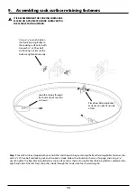
Page 17: ...ced on the right hand side of the tab Next loop the J Hook through the inside slot of each remaining tab n IT IS RECOMMENDED THE COOKING SURFACE BE PLACED ON A PROTECTED WORK SURFACE WITH THE FLANGE FACING UPWARD Place Rear Retaining Bullet Fastener on right hand side of tab Using a 7 16 wrench tighten the Rear Retaining Bullet to the cooking surface tab with two each 1 4 x 20 hex bolt and locking...

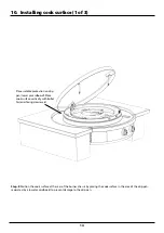
Page 18: ...e rear of the burner chassis by placing the cook surface in the area of the drip pan separated by a towel or cardboard to prevent damage to the drip pan Place suitable protection on drip pan towel or cardboard Place cook surface vertically with Bullet Fastener facing downward ...

Page 19: ... to the right of the rear seam rear view of the chassis skirt A Then rotate the cook surface clockwise until the support tab is in line with the seam B and the rear bullet secures in the chassis slot C COOK SURFACE SUPPORT TAB BOTTOM UP VIEW OF REAR COOK SURFACE CUT AWAY VIEW OF REAR COOK SURFACE SHOWING BULLET ENGAGED IN CHASSIS SLOT A B C REAR BULLET 10 Installing cook surface 2 of 3 ...

Page 20: ...at a time slide J hooks through guide tubes Slowly place cooktop down Open both waste doors and tighten nyloc nut on end of j hook located at inside rear of each waste door Open waste doors to locate end of J hook Guide Tube J Hook Tighten nyloc nut at end of each J hook 10 Installing cook surface 3 of 3 ...

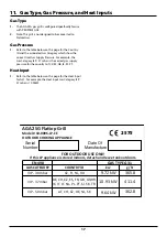
Page 21: ...8 2575 AGA 25G Flattop Grill 11 Gas Type Gas Pressure and Heat Inputs Gas Type 1 The AGA 25G gas grill is configured specifically for use with PROPANE GAS 2 Note This grill is not designed to be converted to Natural Gas Gas Pressure 1 Refer to the table below on this page for the Country ID and the associated Gas Caragory which show the correct Inlet Gas Supply Pressure For example the Gas Catagor...

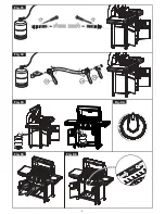
Page 22: ...propane gas regulator has an EN Standard of EN16129 Gas Regulator Hose The type of propane gas hose shall me 8mm in diameter and shall not exceed 1 5m in length n In your own interest and that of safety to comply with the law all gas appliance should be installed by a competant person in accordance with the relevant regulations Step 11 Connect Gas using a suitable LP hose designed for outdoor cook...

Page 23: ...ing To perform a leak check you will need a solution of soap and water and a brush or rag to wet all gas connections 1 Turn all control knobs to the OFF position 2 Turn on gas supply and check for leaks by wetting the connections with the soap and water solution and watching for bubbles If bubbles appear or if a bubble grows there is a leak Note Since some leak test solutions including soap and wa...

Page 24: ...rom the venturi Orifice Retaining Arm Gas Burner Orifice Inner Burner Outer Burner 14 Gas burner and injectors Check to ensure the following items are complete DRIP PAN PROPERLY INSTALLED Ensure that the drip pan half rolled top bead overhangs the cutout dimension by 25 and the black O ring is creating a seal against the countertop DRIP PAN GASKET SECURED Black drip pan gasket should fit properly ...

Page 25: ...21 16 Operating Instructions Please refer to page 22 page 26 before using this AGA outdoor gas grill ...

Page 26: ...rough three positions Either the Inner or the Outer burners may be used independently to support a wide range of cooking techniques Operating only the Inner burner provides direct temperature under the center of the cook surface with indirect heat at the outside edge that is useful for holding temperature and simmering items in a pot or pan Conversely operating only the Outer burner can be used fo...

Page 27: ...ter turn the burner Control Knob off wait 2 minutes and repeat lighting instructions If after repeated attempts and the burner does not ignite follow the manual lighting procedure below Manual Match Lighting Procedure 1 To light the burner manually feed a lit match through one of the flame viewing holes in the burner skirt above the control panel until it is close to the burner 2 Turn the right ha...

Page 28: ... assembly and remove the burners and visually inspect inside the venturi ports If insect nests are found the best method is to use a thin piece of wire or bamboo skewer to remove the obstruction Right Flame Wrong Flame Dark Blue Dark Blue Light Blue Light Blue Yellow Tip Excessive Yellow Tipping 19 Checking Operation If the ignitor does not work you may need to replace the battery 1 Look under the...

Page 29: ...Opening Spillover Tray Doors To open a door grasp the door at its bottom and pull forward n Do not allow spillover liquids or debris down spillover slots when doors are open Any liquids or debris that may fall into this area when doors are open should be immediately wiped with a dry cloth and keep this area clean at all times n Do not allow the spillover trays to overflow and do not allow full tra...

Page 30: ...delicate foods and applications To use a grill cleaning screen With a warm cook surface place one grey polishing pad between the grill handle base and the grill screen so the grill screen makes direct contact with the cooking surface Pour a small amount of vegetable oil on the cook surface and scrub the surface in a circular motion The gray polishing pad allows excess oil to be absorbed and scours...

Page 31: ......
Page 32: ... right to change specifications and make modifications to the appliances described and illustrated at any time www agaliving com www agacookshop co uk AGA Rangemaster Station Road Ketley Telford Shropshire TF1 5AQ England For further advice or information contact your local AGA Specialist ...

Reviews: