background image

Evolution Digital 


EVO-SUP-DMS2002HD-U-001-v1r0 


 Page 75 

Appendix A  Frequency Hunt List 

When in Hunt Mode, the DTA will scan frequencies in a prescribed manner.  The DTA will start with a list of well 

used EIA centered frequencies, and then move to a complete list of EIA centered frequencies.  If the DTA fails to 

lock on any of the EIA centered frequencies it will move to HRC centered frequencies.  The remainder of this 

section details the list of frequencies in the order they are scanned. 

/* Well Known List of EIA Centered Frequencies (kHz) */ 

567000, 573000, 579000, 585000, 591000, 651000, 657000, 489000, 495000, 807000, 565750, 571750 

/* Complete list of EIA Centered Frequencies (kHz)*/  

57000, 63000, 69000, 85000, 177000, 183000, 189000, 195000, 201000, 207000, 213000, 123000, 129000, 135000, 

141000, 147000, 153000, 159000, 165000, 171000, 219000, 225000, 231000, 237000, 243000, 249000, 255000, 

261000,  267000, 273000, 279000, 285000, 291000, 297000, 303000, 309000, 315000, 321000, 327000, 333000, 

339000, 345000, 351000, 357000, 363000, 375000, 381000, 387000, 393000, 399000, 405000, 411000, 417000, 

423000, 429000, 435000, 441000, 447000, 453000, 459000, 465000, 471000, 477000, 483000, 489000, 495000, 

501000, 507000, 513000, 519000, 525000, 531000, 537000, 543000, 549000, 555000, 561000, 567000, 573000, 

579000, 585000, 591000, 597000, 603000, 609000, 615000, 621000, 627000, 633000, 639000, 645000,  93000,  

99000, 105000, 111000, 117000, 651000, 657000, 663000, 669000, 675000, 681000, 687000, 693000, 699000, 

705000, 711000, 717000, 723000, 729000, 735000, 741000, 747000, 753000, 759000, 765000, 771000, 777000, 

783000, 789000, 795000, 801000, 807000, 813000, 837000, 843000, 849000, 855000, 861000 

/* HRC Centered Frequencies (kHz)*/ 

58750,  64750,  70750,  86750, 178750, 184750, 190750, 196750, 202750, 208750, 214750, 124750, 130750,  

36750, 142750, 148750, 154750, 160750, 166750, 172750, 220750, 226750, 232750, 238750, 244750, 250750, 

256750, 262750, 268750, 274750, 280750, 286750, 292750, 298750, 304750, 310750, 316750, 322750, 328750, 

334750, 340750, 346750, 352750, 358750, 364750, 370750, 376750, 382750, 388750, 394750, 400750, 406750, 

412750, 418750, 424750, 430750, 436750, 442750, 448750, 454750, 460750, 466750, 472750, 478750, 484750, 

490750, 496750, 502750, 508750, 514750, 520750, 526750, 532750, 538750, 544750, 550750, 556750, 562750, 

568750, 574750, 580750, 586750, 592750, 598750, 604750, 610750, 616750, 622750, 628750, 634750, 640750, 

646750,  94750, 100750, 106750, 112750, 118750, 652750, 658750, 664750, 670750, 676750, 682750, 688750, 

694750, 700750, 706750, 712750, 718750, 724750, 730750, 736750, 742750, 748750, 754750, 760750, 766750, 

772750, 778750, 784750, 790750, 796750, 802750, 808750, 814750, 820750, 826750, 832750, 838750, 844750, 

850750, 856750, 862750 

Summary of Contents for HD uDTA

Page 1: ...HD uDTA INSTALL Resource Book 2013 Evolution Digital LLC This document contains confidential and privileged material for the sole use of the intended recipient ...

Page 2: ...Guide Liberty HD uDTA Wall Plate Device Installation HD uDTA Traning Presentation HD uDTA Technical User Guide 2013 Evolution Digital LLC This document contains confidential and privileged material for the sole use of the intended recipient ...

Page 3: ...HD uDTA Customer Facing User Guide 2013 Evolution Digital LLC This document contains confidential and privileged material for the sole use of the intended recipient ...

Page 4: ...toves or other apparatus including amplifiers that produce heat 9 Do not defeat the safety purpose of the polarized or grounding type plug A polarized plug has two blades with one wider than the other A grounding type plug has two blades and a third grounding prong The wide blade or the third prong is provided for your safety When the provided plug does not fit into your outlet consult an electric...

Page 5: ...main plug from the apparatus if it s defective And please call a repair man in your location When used outside of the U S it may be used HAR code with fittings of an approved agency is employed CAUTION These servicing instructions are for use by qualified service personnel only To reduce the risk of electric shock do not perform any servicing other than that contained in the operating instructions...

Page 6: ... language if available TV must be programed with the remote LED Indicator Button press and special command indication TV Power Turn your TV on or off Last Return to the previous channel or menu Exit Return to watching TV Page Down Now Next page down Channel Channel up down Mute Sound on off Red C Toggles through available closed captioning Setup Program your remote control to your STB and TV NOTE ...

Page 7: ...for more detailed instruction on the remote control and batteries Refer to page 11 for instructions to pair your remote control What if I forgot my PIN Code Contact your cable provider and they will be able to reset them back to the default That will allow you to enter a new PIN code Refer to page 13 to learn how to change your PIN code How do I control what my child watches You can restrict viewi...

Page 8: ...Liberty HD uDTA Wall Plate Device Installation 2013 Evolution Digital LLC This document contains confidential and privileged material for the sole use of the intended recipient ...

Page 9: ...connect coax cable to Liberty with the keyhole at the top Connect the HDMI and power supply cords Hook Liberty keyhole mount on top screw Liberty installed Screw the Liberty to the wall with the screw and washer provided Bypass port to connect secondary devices such as DVR or cable modem optional RF Output LED Light Bottom Screw Hole Set desired RF channel Insert plug to cover screw hole Evolution...

Page 10: ...HD uDTA Training Presentation 2013 Evolution Digital LLC This document contains confidential and privileged material for the sole use of the intended recipient ...

Page 11: ...8 13 12 2013 Evolution Digital LLC All Rights Reserved Confidential information Modes of Operation Boot Hunt Pending Initialization Normal Operations Code Download Trouble ...

Page 12: ...on Boot Mode Occurs when power is applied or when DTA has been reset either manually or via headend messaging Function Validate launch code image LED Status None Valid Mode Transitions Hunt Mode if code image is successfully validated Trouble Mode if code image fails validation ...

Page 13: ...tion Hunt Mode Occurs when the DTA has completed Boot Mode and successfully validated and loaded the active code image Function Search for QAM with CAT PID and valid CA system ID LED Status Continuous blink Valid Mode Transition Pending Initialization upon receipt of CAT PID ...

Page 14: ...e When the DTA first enters Hunt Mode it will scan a list of well known DTA frequencies 567 573 579 585 591 651 657 489 495 807 565 750 and 571 750 MHz If the DTA does not lock on to any of those frequencies it will start hunting at 57 MHz and increment by 6 MHz until it finds a valid QAM ...

Page 15: ...8 13 12 2013 Evolution Digital LLC All Rights Reserved Confidential information Hunt Mode On Screen Message ...

Page 16: ...hen the DTA has transitioned from Hunt mode by finding a CAT PID with a valid CA system ID Function Verifying CA parameters found in hunt mode monitoring network PID for SI monitoring EMM PID for headend messaging LED Status Two blinks repeated continuously Valid Mode Transitions Code Download Boot Normal Operations ...

Page 17: ...8 13 12 2013 Evolution Digital LLC All Rights Reserved Confidential information Pending Initialization Mode On Screen Message ...

Page 18: ...as transitioned from Pending Initialization mode by receiving the proper configuration and activation messages and has loaded a channel map Function Decoding A V Monitoring SI data and EMM messages and remote control commands LED Status Solid green no blinking Valid Mode Transitions Pending Initialization Code Download Boot ...

Page 19: ...load Mode Occurs when the DTA has detected a valid CVT indicating that a newer version of code is available for download Function Download new code image LED Status Three blinks followed by a long pause Valid Mode Transitions Boot upon successful download previous mode upon failed download ...

Page 20: ...8 13 12 2013 Evolution Digital LLC All Rights Reserved Confidential information Code Download On Screen Message ...

Page 21: ...ial information Trouble Mode Occurs when the bootloader fails to validate the DTA code image The DTA will only enter trouble mode from boot mode LED Status Continuous short blink Valid Mode Transitions None the DTA must be reset in order to re attempt a proper boot ...

Page 22: ... To access the diagnostics menu hold down the 7 button on the remote control note that the diagnostics menu can be accessed in any mode except Boot and Trouble Although there are a large number of options this presentation will only cover those that will be most useful in troubleshooting the DTA ...

Page 23: ...8 13 12 2013 Evolution Digital LLC All Rights Reserved Confidential information Diagnostics Menu ...

Page 24: ...8 13 12 2013 Evolution Digital LLC All Rights Reserved Confidential information General Info Menu This menu gives key information about the DTA including hardware version unit ID MAC address etc ...

Page 25: ...13 Evolution Digital LLC All Rights Reserved Confidential information HD DTA Status Menu 1 This menu gives information on the status of the DTA including the activated status as well as the current operating mode ...

Page 26: ...8 13 12 2013 Evolution Digital LLC All Rights Reserved Confidential information HD DTA Status Menu 2 The second page of the HD DTA Status menu gives information about the time configuration of the DTA ...

Page 27: ...13 Evolution Digital LLC All Rights Reserved Confidential information Tuner Status Menu This menu tells you what frequency the DTA is currently tuned to and gives information about the power level SNR and CAT PID ...

Page 28: ...This screen gives details about the currently tuned channel including its frequency modulation and program number as well as which audio and video PIDs are present The channel can be changed real time while viewing this menu by either direct channel entry or by using the CH up down buttons on the remote ...

Page 29: ...8 13 12 2013 Evolution Digital LLC All Rights Reserved Confidential information Current Channel Status ...

Page 30: ... map menu gives a listing of the entire channel map loaded on the DTA Each service is listed by its display virtual channel number and includes its display name frequency and program number The virtual channel map will likely be several pages long and can be navigated using the up and down arrows on the remote control ...

Page 31: ...8 13 12 2013 Evolution Digital LLC All Rights Reserved Confidential information Virtual Channel Map ...

Page 32: ... 2013 Evolution Digital LLC All Rights Reserved Confidential information Received Messages The received messages menu shows real time counters of all messages that have been received from the headend controller ...

Page 33: ...ts This screen displays the name of the currently loaded code object SW version There are two code banks Bank A and Bank B If both banks display a code name then the bank with the asterisk next to it is the SW that the DTA is currently running and the other bank is the previously loaded SW ...

Page 34: ...8 13 12 2013 Evolution Digital LLC All Rights Reserved Confidential information Code Objects ...

Page 35: ...f a problem is reported in the field then pictures of the following diagnostic menus should be provided to Evolution HD DTA Status Tuner Status while the DTA is tuned to the problematic channel or channels Current Channel Status of the problematic channel or channels Code Objects Received Messages ...

Page 36: ...8 13 12 2013 Evolution Digital LLC All Rights Reserved Confidential information Troubleshooting Additionally a full QAM capture capture of the RF input to the DTA may be required ...

Page 37: ...g Additionally a full QAM capture capture of the RF input to the DTA may be required When all of this information has been gathered please contact Evolution support at support evolutionbb com for further instructions Note that the two steps listed above should be completed by headend personnel ...

Page 38: ...DTA can be manually reset to its factory default settings by taking the following steps note that the currently loaded SW will remain the same but all other values including the channel map and activation status of the DTA will be reset Enter the diagnostics menu by holding 7 on the remote control ...

Page 39: ... 12 2013 Evolution Digital LLC All Rights Reserved Confidential information Factory Reset Once you are in the diagnostics menu press the info button on the remote control to display the following hidden menu ...

Page 40: ...erved Confidential information Factory Reset The Reset to Factory Defaults option will be highlighted by default so just press the OK button on the remote control to complete the process After a successful reset the DTA will reboot and enter hunt mode ...

Page 41: ...8 13 12 2013 Evolution Digital LLC All Rights Reserved Confidential information Remote ...

Page 42: ... Remote Pairing The remote delivered with the DTA is capable of RF pairing so that a customer may hide the device and still be able to control it To pair the remote take the following steps note that line of sight is required between the remote and the DTA during the pairing process ...

Page 43: ...2 2013 Evolution Digital LLC All Rights Reserved Confidential information RF Remote Pairing Enter the Setup menu by pressing the Menu button on the remote and then select Remote Control and press the OK button ...

Page 44: ...2 2013 Evolution Digital LLC All Rights Reserved Confidential information RF Remote Pairing After you select Remote Control Pairing you will see a popup screen with instructions on how to complete the process ...

Page 45: ...13 Evolution Digital LLC All Rights Reserved Confidential information RF Remote Pairing Hold the Setup button on the remote until the LED turns green and then press the Menu button to bring up the code entry popup ...

Page 46: ...e you enter the pairing code you will be presented with the pairing success message and the remote will operate in RF mode note that IR will no longer be transmitted Also note that the DTA will always be able to receive IR commands as a failsafe regardless of whether or not a remote is paired with it ...

Page 47: ...8 13 12 2013 Evolution Digital LLC All Rights Reserved Confidential information RF Remote Pairing ...

Page 48: ...e are several special remote codes that can be used to change the mode of operation of the remote control To unpair the remote hold setup until the LED turns green and press 9 8 7 If the code is entered successfully the LED will blink green two times and the remote will be unpaired and operate in IR mode ...

Page 49: ...nfidential information Special Remote Codes To reset the TV IR code hold setup until the LED turns green and then enter 9 8 6 If the code is entered successfully the LED will blink green two times and the remote will no longer be able to control the television ...

Page 50: ... To factory reset the remote hold setup until the LED turns green and then enter 9 8 1 If the code is entered successfully the LED will blink green two times and the remote will be reset to factory defaults all RF pairing information and TV control will be reset and the remote will operate in IR mode ...

Page 51: ...HD uDTA Technical User Guide 2013 Evolution Digital LLC This document contains confidential and privileged material for the sole use of the intended recipient ...

Page 52: ... DMS 2002HD U User Guide Evolution Digital LLC 7347 S Revere Parkway Building A Centennial CO 80112 www evolutionbb com 800 315 2253 ...

Page 53: ...nt Mode 14 2 3 1 QAM Search 16 2 3 1 1 CA System ID 17 2 3 1 2 Network PID 17 2 3 2 Hunt Mode On Screen Messages 17 2 3 3 Mode Transitions 19 2 4 Pending Initialization Mode 19 2 4 1 CA Values check 21 2 4 2 DTA Activation and Configuration 21 2 4 2 1 Transition to Normal Operations 22 2 4 3 Network PID Monitoring 23 2 4 3 1 VCT ID Assignment 23 2 4 4 Pending Initialization Mode On Screen Messages...

Page 54: ...2 6 4 1 Failed Code Downloads 34 2 6 5 Code Download Mode On Screen Message 36 2 6 6 Interruption to Code Download 36 2 6 7 Mode Transitions 36 2 7 Trouble Mode 37 2 7 1 Mode Transitions 37 3 0 Channel Maps 37 3 1 Channel Types Supported 37 3 1 1 Channel Numbers 38 3 1 2 Channel Name 38 3 2 Channel Map Updates 39 3 2 1 Addition of Channels 39 3 2 2 Removal of Channels 40 3 2 2 1 Changes Made to Cu...

Page 55: ...44 6 0 Diagnostic Menu 45 6 1 Navigating the Diagnostic Menu 45 6 2 Main Diagnostic Screen 45 6 3 General Info 46 6 4 HD DTA Status 47 6 5 MSO Info 51 6 5 1 MSO Info Customization 52 6 6 Tuner Status 54 6 7 Current Channel Status 56 6 8 Virtual Channel Map 58 6 9 Received Messages 60 6 10 Code Objects 62 6 11 Code Download 63 6 12 HDMI 65 7 0 Evolution Digital Defined 67 7 1 SI Descriptors 68 7 2 ...

Page 56: ...ge 5 8 1 Hunt Mode 73 8 2 Manual Clear 73 Appendix A Frequency Hunt List 75 Appendix B Default NVRAM Values 76 Appendix C Additional DTA Screenshots 77 Appendix D DTA Headend Messages 79 D 1 DTA Configuration Message 79 D 2 DTA Operations Messages 79 ...

Page 57: ... Reset Types and their Effect on the DTA 41 Table 11 Effects on Parameters Across DTA Reset Types 42 Table 12 Useable Remote Buttons While In Diagnostic Menu 45 Table 13 General Info Screen Parameters 46 Table 14 HD DTA Status Screen Parameters 48 Table 15 MSO Info Screen Parameters 51 Table 16 Tuner Status Screen Parameters 54 Table 17 Current Channel Status Screen Parameters 56 Table 18 Virtual ...

Page 58: ...ng Init 24 Figure 10 Activation Support Message Cable Operator Defined Custom Message 25 Figure 11 Activation Support Message Default Message 26 Figure 12 DTA Status Normal Operations Mode Screen 1 of 2 28 Figure 13 DTA Status Normal Operations Mode Screen 2 of 2 28 Figure 14 Interruption During Normal Operations 29 Figure 15 DTA Status Diagnostic Screen During Code Download 31 Figure 16 Code Down...

Page 59: ...r 53 Figure 32 Diagnostic Menu MSO Info Screen 1 with modified MSO Phone Number 53 Figure 33 Service Interruption Message with Customized MSO Phone Number 54 Figure 34 Diagnostic Menu Tuner Status 56 Figure 35 Diagnostic Menu Current Channel Status 58 Figure 36 Diagnostic Menu Virtual Channel Map 60 Figure 37 Diagnostic Menu Received Messages 62 Figure 38 Diagnostic Menu Code Objects 63 Figure 39 ...

Page 60: ...Page 9 Figure 47 DTA On Screen Information Channel Info 77 Figure 48 DTA On Screen Information Volume Bar 77 Figure 49 DTA On Screen Information Muted Volume Bar 78 Version Control Version Date Notes Author 1 0 06 15 2012 Initial Release A Schneider ...

Page 61: ...rator technicians and customer support personnel 1 1 Terms and Abbreviations Table 1 List of Terms and Abbreviations A V Audio Video CAT Conditional Access Table CDS Carrier Definition Subtable CVT Code Version Table DCM Defined Channels Map EAS Emergency Alert System IR Infrared MMS Modulation Mode Subtable PAT Program Association Table PCR Program Clock Reference PID Packet Identifier PMT Progra...

Page 62: ...tails on the various operating modes of the DTA Section 3 discusses specifics on channel maps including channel types supported and updating the channel map Section 4 discusses resetting the DTA including types of resets effects on stored parameters and how the DTA recovers from resets Section 5 discusses EAS Section 6 discusses the Diagnostic Menu in detail including what all the parameters are t...

Page 63: ... in and out of each mode 2 1 High Level Overview To achieve Normal Operations the DTA will make its way through Boot Hunt and Pending Initialization modes as shown in Figure 1 Will progressing through each mode certain conditions need to be met to proceed to the next mode It is important to note that the DTA will always follow the same path after a reboot message from the headend or power cycle Th...

Page 64: ...n Boot Mode the DTA will validate the active code image Once validated the DTA will launch the image After launching the image the DTA will transition to Hunt Mode If the DTA does not validate the code image it will transition to Trouble Mode Table 2 details the properties of Boot Mode Table 2 Boot Mode Properties Mode activities Validate code image Valid Mode Transition s Hunt Mode Trouble Mode L...

Page 65: ...ode Resets are discussed more in Section 4 0 2 2 2 Mode Transitions The DTA will transition from Boot Mode to Hunt Mode after successfully validating a stored image The DTA will transition from Boot Mode to Trouble Mode if it fails to validate a stored image 2 3 Hunt Mode The DTA will enter Hunt Mode from Boot or Pending Initialization Modes please see these respective sections for more details ab...

Page 66: ...ure 2 shows the DTA Status diagnostic screen while the DTA is in Hunt Mode Please note the DTA should not be sent an activation and or configuration message while in Hunt Mode These messages should only be sent when the DTA is in Pending Initialization Mode Figure 2 DTA Status Hunt Mode Figure 3 shows the Tuner Status diagnostic screen while the DTA is in Hunt Mode ...

Page 67: ... list has been created to help speed up the initial installation of the DTA on a cable network Upon locking to a QAM the DTA will wait 3 seconds for a CAT PID containing a valid CA system ID It is expected the CAT PID will be 0x01 decimal 1 If the CAT PID is found and it contains a valid CA system ID the QAM will be stored as the Turn On QAM and the DTA will transition to Pending Initialization Mo...

Page 68: ... searching for Program 0 zero in the Program Association Table PAT The PID associated with Program 0 will be stored as the Network PID If the DTA does not find a Program 0 in the PAT it will use 0x1FFC as the Network PID The Network PID value being used can be found in the Tuner Status diagnostic screen ensure the DTA is in Pending Initialization mode prior to checking for the Network PID 2 3 2 Hu...

Page 69: ...terations through the predefined frequency list detailed in Appendix A Frequency Hunt List Table 4 shows how the percentage values line up with the frequency list Table 4 Hunt Mode Progress Bar Percentages Percentage Complete Frequency List scanned 0 Scan started 25 First iteration through frequency list half way through 50 First iteration through frequency list completed 75 Second iteration throu...

Page 70: ... OSD and display a screen saver to prevent plasma screen burn in 2 3 3 Mode Transitions The DTA will transition from Hunt Mode to Pending Initialization Mode as described in this section 2 4 Pending Initialization Mode The DTA enters Pending Initialization Mode also known as Pending Init from Hunt Normal Operations or Common Download Modes please see these respective sections for more details abou...

Page 71: ...ated continuously A V Decode None Diagnostics Available IR Input Available In band Message Processing Network and EMM PIDs Once the DTA is in Pending Init Mode the DTA can be sent activation and configuration messages The DTA will remain in Pending Init Mode until it is Activated with a proper configuration message from the headend and has downloaded the full channel map it is assigned to Figure 7...

Page 72: ...alues does not match the respective stored values the DTA will set its Activation Flag to No After the comparison the DTA will set the stored values to the temporary values Please note the EMM Provider ID is not required for normal operations The EMM PID value is set according to what is defined in the CAT 2 4 2 DTA Activation and Configuration The DTA controller in the cable headend will provide ...

Page 73: ... Normal Operations Figure 8 below shows an example of the DTA Status screen when the DTA is in Normal Operations mode Figure 8 DTA Status Screen Normal Operations 2 4 2 1 Transition to Normal Operations Table 6 below details the condition that must be met in order for the DTA to transition to Normal Operations Mode and the combination of states and conditions that keep the DTA in Pending Initializ...

Page 74: ...ed with SCTE 65 Profile 2 It is highly suggested that all QAMs carrying DTA services carry the Network PID and SI tables In this way it will be assured the DTA will receive channel map updated and code download triggers 2 4 3 1 VCT ID Assignment By default the DTA is looking for SI associated with VCT ID 0 until a message from the headend indicates otherwise The DTA will filter the Network PID and...

Page 75: ...appear for 5 seconds or until the box detects a Site Announcement message containing customized text for the Activation Support message It is recommended that the headend be configured to send a Site Announcement message at least once every 5 seconds so the initial Activation Support message can be updated with the Cable Operator s desired custom message Please consult with your headend equipment ...

Page 76: ...ontinuing is the text that is fully customizable by the Cable Operator this is commonly referred to as the MSO Phone Number field For more information on the use of this field please see Section 6 5 1 Please note this is just an example and used for illustration purposes If after 5 seconds the DTA does not detect a Site Announcement message then it will display the factory default message as shown...

Page 77: ... Section 2 4 2 1 The DTA will transition from Pending Initialization Mode to Hunt Mode if it does not receive a CAT with a CA System ID matching its currently stored value in a five 5 minute period 2 5 Normal Operations Mode The DTA enters Normal Operations Mode Pending Initialization Mode or Common Download Mode please see these respective sections for more details about how the DTA enters Normal...

Page 78: ... blinking at all A V Decode Full decode Diagnostics Available IR Input Available In band Message Processing Network and EMM PIDs While in Normal Operations Mode the DTA may transition to Pending Initialization Common Download and Boot modes Figure 12 and Figure 13 shows the DTA Status diagnostic screens when the DTA has reached Normal Operations Mode Please note that the values shown in the figure...

Page 79: ...Evolution Digital EVO SUP DMS2002HD U 001 v1r0 Page 28 Figure 12 DTA Status Normal Operations Mode Screen 1 of 2 Figure 13 DTA Status Normal Operations Mode Screen 2 of 2 ...

Page 80: ...pdate its channel map when it detects a new version of channel map is available or assigned to a new VCT ID This topic is discussed in more detail in Section 3 0 2 5 3 Interruption to Service In the event service is interrupted the DTA will display an on screen message as shown in Figure 14 Please note that the message shown in Figure 14 is for illustrative purposes only and can be modified by the...

Page 81: ...detects a new version of code is available for download The DTA enters Code Download Mode from Pending Initialization or Normal Operations Mode In Code Download Mode the DTA will perform the code download function and block all video and audio decoding It will however allow the user to enter the diagnostic menu Table 8 details the properties of Normal Operations Mode Table 8 Code Download Mode Pro...

Page 82: ...ils to download the code the DTA will return to its previous mode of operation Figure 15 shows the DTA Status diagnostic screen when the DTA has entered Code Download Mode Please note that the values shown in Figure 15 may not match those in your DTA and is used only as an illustration for the DTA Status screen Figure 15 DTA Status Diagnostic Screen During Code Download Figure 16 shows the Code Do...

Page 83: ...le for download The DTA does not support delivery of the CVT via a DSG tunnel 2 6 2 CVT Configuration Count The DTA will monitor the CVT configuration count value By default the CVT configuration count value is set to 0 The DTA applies the default value to the CVT Config Count Change parameter in the Code Download diagnostic screen when the DTA is reset either through power cycle or headend messag...

Page 84: ...e DTA will attempt to associate the Source ID received in the CVT with a Source ID in the channel map If it fails to make an association because there is no channel map or there is no entry in the channel map matching the Source ID the DTA will not attempt to download the code 2 6 2 2 Location Value 1 The DTA supports Location Value in the CVT of 1 one The DTA will attempt to tune to the Frequency...

Page 85: ...a carousel as specified in Ref 1 Evolution Digital will provide the binary file necessary to perform the code download The operator is responsible for creating the carousel and CVT 2 6 4 Code Download Retry The DTA will attempt to download or validate the new image a total of three times If after three attempts of trying to download or validate code the DTA fails the DTA will return to the previou...

Page 86: ...In Figure 19 the failure is due to file download failure Note that the DTA failed to download the code three times This is shown by the Download Failure Count equaling three 3 Figure 19 Code Download Failure File Download Failure Please see Section 6 11 for more information on all possible Download Status messages ...

Page 87: ...n After the power cycle the CVT Configuration Count value will be set to 0 Since the CVT configuration count streaming from the headend is a non zero value if there is new code to download the DTA will start the code download process all over again Please note that if there were previous failures in the code download power cycling the box may not resolve those issues That may require reconfigurati...

Page 88: ...sition s None Box must be rebooted LED status Three blinks then long pause A V Decode None Diagnostics Not Available IR Input Not Available In band Message Processing Continuous short blink 2 7 1 Mode Transitions There are no mode transitions from Trouble Mode The DTA must be power cycled to attempt another boot up 3 0 Channel Maps The DTA supports channel maps delivered in SCTE 65 tables in band ...

Page 89: ... DTA supports 4 digit channel numbers with a maximum channel number of 4095 In the Virtual Channel Map VCM table of the SI data the virtual channel field is 12 bits long resulting in a maximum value of 4095 3 1 2 Channel Name The DTA displays a channel name The channel name length is capped at 14 characters The character map includes all valid alphanumeric and symbolic characters Figure 21 shows a...

Page 90: ... to that shown in Figure 22 Notice that the Stored VCT ID is Loaded The second line represents the VCT ID of the channel map that is currently loaded and active note the VCT IDs match Please note that the VCT ID values used in your system may be different than the values shown in the figure The figure is for illustration purposes only Figure 22 Virtual Channel Map Diagnostic Screen Channel map loa...

Page 91: ... to the viewer the DTA will provide the following delayed service interruption message to the viewer Figure 23 Delayed Service Interruption Message 3 2 3 Change of VCT ID When the DTA is assigned to a new VCT ID through a headend message the DTA Virtual Channel Map diagnostic screen will look similar to that shown in Figure 24 The Stored VCT ID in this case represents the new VCT ID the DTA is ass...

Page 92: ...ade since it was last viewed 4 0 DTA Reset The DTA can be reset in multiple ways Table 10 shows the types of resets that can be delivered to the DTA Please note that the headend controller may not have an exact command available to reset the DTA in the manner described Please consult the headend controller vendor for more details on how to remotely reset the DTA and what commands to use Table 10 R...

Page 93: ...Warm VCT ID Save Clear Save SI Tables Clear Clear Save Turn On QAM Save Clear Save Configured Location ID Save Clear Save Configured Timezone Save Clear Save Configured Daylight Savings Entry Save Clear Save Configured Daylight Savings Exit Save Clear Save Configured MSO Phone Number Save Clear Save Configured Timeout Value Parameter Save Clear Save Timeout Counter Parameter Save Clear Save Networ...

Page 94: ...4 1 1 Recovery from Initialization Upon boot up the DTA will not have a channel map First it will determine the network PID from the Turn On QAM it is tuned to The DTA will then automatically acquire the channel map for its stored VCT ID 4 1 2 Recovery from Cold Reset A cold reset is essentially a return to factory reset Upon boot up the DTA will enter Hunt Mode and proceed through the Pending Ini...

Page 95: ...he alert channel 5 2 Exceptions List The DTA supports an exception list Meaning if the DTA is tuned to a channel that is included in the exception list delivered with the EAS message configured in the headend the DTA will not tune to the alert channel It will ignore the EAS message 5 3 Force Tune Behavior Upon reception of an EAS message containing a priority of 1 or greater the DTA will force tun...

Page 96: ...are not useable in anyway while in the Diagnostic Menu Table 12 Useable Remote Buttons While In Diagnostic Menu Button Use Channel Up Down Move selection arrow up or down Enter Select item Info Exit Diagnostic menu Last Return to previous screen Please note that throughout the remainder of this section screen shots will be used as illustrations of the various diagnostic screens These are just exam...

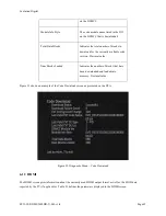
Page 97: ... that appears after the diagnostic screen is invoked Please note there is not information reported on this screen Figure 25 Diagnostic Menu Main Menu 6 3 General Info General Info screen provides unit specific information Table 13 defines the parameters displayed on the General Info screen Table 13 General Info Screen Parameters Parameter Description Vendor Name Evolution vendor name Always ...

Page 98: ... unique Unit Address MAC Address Assigned unique MAC Address Figure 26 shows an example of the General Info screen as presented on the DTA Figure 26 Diagnostic Menu General Info 6 4 HD DTA Status The DTA Status screen indicates the current mode of the DTA as well as provides the current configuration of the DTA including activation status Table 14 defines the parameters displayed on the DTA Status...

Page 99: ...in hours DTA counts down by 2 hours if it does not receive appropriate headend messages in the allotted period of time Config Max LocID Error Count Maximum number of times the DTA can receive a headend message with different location ID LocID Current LocID Error Count Current number of times the DTA has received a headend message with a different LocID Once this value reaches the configured maximu...

Page 100: ... by the DTA in an STT Time Zone The configured timezone from a headend message Daylight Savings Entry The date and time when the DTA will enter Daylight Savings Time as configured by the headend Daylight Savings Exit The date and time when the DTA will exit Daylight Savings Time as configured by the headend Last Addressable Timestamp Date and time for when the last addressable message was received...

Page 101: ...l EVO SUP DMS2002HD U 001 v1r0 Page 50 Figure 27 and Figure 28 show examples of the DTA Status screens as presented on the DTA Figure 27 Diagnostic Menu DTA Status Screen 1 Figure 28 Diagnostic Menu DTA Status Screen 2 ...

Page 102: ...splayed in the MSO Info screens Table 15 MSO Info Screen Parameters Parameter Description Service Interruption Message The current service interruption message that will be displayed on screen by the DTA Activation Support Message The current activation support message that will be displayed on screen by the DTA Figure 29 and Figure 30 show examples of the MSO Info screens as presented on the DTA ...

Page 103: ...tomized to a certain extent with information from the headend controller Specifically there is an MSO Phone Number field that can be set by the operator Please consult with your headend controller manufacture for modification of the MSO phone number field to understand its effect on the DTA on screen messaging for service interruptions and activation support ...

Page 104: ...e customized to replace the default text below We ve detected an interruption in your service with text and or a phone number The following figures illustrate how the MSO Phone Number field has been modified with new text and a phone number for the Service Interruption Message Figure 32 Diagnostic Menu MSO Info Screen 1 with modified MSO Phone Number ...

Page 105: ...tivation Support Messages 6 6 Tuner Status The Tuner Status screen provides information on the currently tuned to QAM and indicates if CAT and Network PIDs are present Table 16 defines the parameters displayed in the Tuner Status screen Table 16 Tuner Status Screen Parameters Parameter Description Tuner Frequency Currently tuned to frequency in MHz Power Level dBmV Power level of the currently tun...

Page 106: ... Once CAT PID is found with a valid CA System ID CA SysID the DTA will display the EMM Provider ID PAT Present Indicates if PAT is present on the tuned to QAM Network PID Indicates the Network PID being used on the currently tuned to QAM May change for each QAM if the operator configures some QAMs to use different network PID then others If the DTA does not find Program 0 in the PAT referencing a ...

Page 107: ...hat while viewing the Current Channel Status screen you can change channels using the CH up down buttons or by direct channel entry This will allow you to see information for any channel in your lineup Table 17 defines the parameters displayed in the Current Channel Status screen Table 17 Current Channel Status Screen Parameters Parameter Description Current VC Indicates the virtual channel VC of ...

Page 108: ...e service that are carrying audio and what language they are language based on ISO 639 Hex value An asterisk is placed next to the audio PID that has been selected by the user Audio User Muted Indicated if the user has muted audio on the DTA Decryption Error If the DTA is tuned to an encrypted channel but cannot decrypt it for some reason the value will be Yes Note that this is not related to the ...

Page 109: ...ID is being downloaded Table 18 defines the parameters displayed in the Virtual Channel Map screen Table 18 Virtual Channel Map Screen Parameters Parameter Description Stored VCT ID Indicates the VCT ID of the channel map assigned to the DTA In both Hex and decimal values If the channel map for this VCT ID is fully loaded the word Loaded will appear after it If the channel map for this VCT ID is c...

Page 110: ...ned as a hidden channel eg common download carousel the VC will have an asterisk next to it SrdID Source ID unique to each service SrcName Source Name as defined in the SCTE 65 SI server CDSRef CDS Reference QAM frequency carrying this service QAM Modulation mode either 64 or 256 Prog MPEG Program number for the service Figure 36 shows an example of the Virtual Channel Map screen as presented on t...

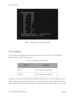
Page 111: ...ovide useful information indicating if the DTA is receiving data on the Network PID as well as messages from the headend Table 19 defines the parameters displayed in the Received Messages screen Table 19 Received Messages Screen Parameters Parameter Description CDS Count of the number of CDS tables received by the DTA MMS Count of the number of MMS tables received by the DTA SNS Count of the numbe...

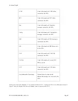
Page 112: ... received by the DTA EM Count of the number of EMMs received by the DTA CAT Count of the number of CAT PIDs received by the DTA CAT Err Count of the number of errored CAT PIDs received CVT Count of the number of CVT tables received by the DTA Last Addressable Timestamp Date and time for when the last addressable message was received by the DTA In this screen if you press the number 0 all counters ...

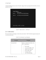
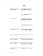
Page 113: ...ble 20 Code Objects Screen Parameters Parameter Description Bank A Name of object stored in Bank A Bank B Name of object stored in Bank B The Bank with the object that is currently loaded will have an asterisk next to it The user cannot select which object to load after the next reset It is possible to have only one object loaded in memory When a new version of code is available the DTA will downl...

Page 114: ...ts 6 11 Code Download The Code Download screen displays the state of the code download Table 21 defines the parameters displayed in the Code Download screen Table 21 Code Download Screen Parameters Parameter Description Download Status Indicates current download status of the DTA Valid values are Not Attempted Cannot Locate DSM CC PID Cannot Locate Code Image File Download Failure Not Enough Memor...

Page 115: ...alue is 3 and then the DTA will stop attempting to download the code After a successful code validation this value will be set to 0 CVT Config Count Change Indicates the value of the configuration count change in the last successfully processed CVT After each reset of the DTA this parameter will be set to 0 Last Valid CVT Code Nam The code file name in the last successfully processed CVT Last Vali...

Page 116: ...ersion Decimal value Num Blocks Loaded Indicates the number of blocks that have been downloaded and loaded into memory Decimal value Figure 39 shows an example of the Code Download screen as presented on the DTA Figure 39 Diagnostic Menu Code Download 6 12 HDMI The HDMI screen gives information about the currently used HDMI output format as well as the EDID data reported by the TV if applicable Ta...

Page 117: ... copy protection is enabled Output Format The current output format resolution Aspect Ratio The current output aspect ratio 16 9 or 4 3 EDID Data Under the EDID Data entry there is a list of the four combinations of supported output formats To the right of each entry will be either a Yes or a No depending on whether or not the connected TV supports each output Figure 39 shows an example of the HDM...

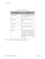
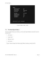
Page 118: ... Digital Defined The Evolution Digital Defined option will take you to the Evolution Digital Defined sub menu which contains the following options SI Descriptors Decoder Status RF Remote Control EAS Location Figure 41 shows an example of the Evolution Digital Defined sub menu as presented by the DTA ...

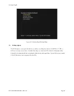
Page 119: ... gives information on whether or not flags have been set for MPEG 4 3D HD or SDV on a service by service basis Note that these flags are set by the SCTE 65 Service Information tables delivered by the headend and that your particular headend may not support them Figure 42 shows an example of the SI Descriptors screen as presented by the DTA ...

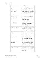
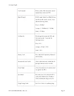
Page 120: ...rol The RF Remote Control screen displays different parameters related to the RF remote control Note that if no remotes are paired then the menu will only display the first page Table 23 RF Remote Control Screen Parameters Parameter Description RF4CE MAC Address The MAC address in the DTA that is sent to the remote control for RF communications RF4CE Short Address The short MAC address in the DTA ...

Page 121: ... DTA may use and the of impairment or pollution on that channel Number of Paired Remotes The number of RF remote controls paired with the DTA A maximum of 5 remote controls may be paired at any time Controller Type The remote control type which typically relates to hardware model MAC Address The MAC address of the remote control that is currently being used with the DTA Short Address The short MAC...

Page 122: ...en the DTA and the remote control It can take the following values Poor 80 Average 80 and 140 Good 140 Battery Level The voltage level reported by the remote control battery Instruction Screen Visible True or False indicates whether the RF pairing instruction screen is visible Line of Sight Yes or No indicates if a remote control is in sight of the DTA Just Booted This value is set to Yes when the...

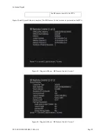
Page 123: ...1r0 Page 72 the RF remote control to the DTA Figure 43 and Figure 44 show examples of the RF Remote Control screens as presented on the DTA Figure 43 Diagnostic Menu RF Remote Control Screen 1 Figure 44 Diagnostic Menu RF Remote Control Screen 2 ...

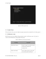
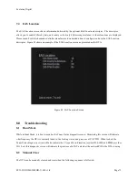
Page 124: ... the EAS Location screen as presented on the DTA Figure 45 EAS Location Screen 8 0 Troubleshooting 8 1 Hunt Mode While in Hunt Mode it is best to monitor the Tuner Status diagnostic screen Monitoring this screen will indicate what frequency the DTA is currently tuned to the locking status and presence of CAT PID When locked the Tuner Status diagnostic screen will also indicate the CA specific info...

Page 125: ...t press the OK button and the box will be cleared and reset After the last step the DTA will clear its NVRAM to the default state and reset itself entering Boot Mode then Hunt Mode if it successfully exits Boot Mode Figure 43 shows an example of the hidden Test Menu as presented on the DTA Figure 46 Test Menu This manual clear process can be used while in the any of the following modes Hunt Pendin...

Page 126: ...531000 537000 543000 549000 555000 561000 567000 573000 579000 585000 591000 597000 603000 609000 615000 621000 627000 633000 639000 645000 93000 99000 105000 111000 117000 651000 657000 663000 669000 675000 681000 687000 693000 699000 705000 711000 717000 723000 729000 735000 741000 747000 753000 759000 765000 771000 777000 783000 789000 795000 801000 807000 813000 837000 843000 849000 855000 861...

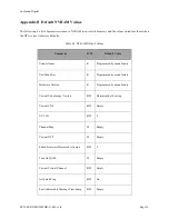
Page 127: ...ult Values Parameter R W Default Value Vendor Name R Programmed by manufacture Unit Identifier R Programmed by manufacture Hardware Version R Programmed by manufacture Current Code Image Version R W Determined at boot up Current CDS R W Empty VCT ID R W 0 Channel Map W Empty Current NTT W Empty Failed Firmware Download Attempts R W 0 Turn On QAM W Empty Current Virtual Channel R W Empty Activated ...

Page 128: ... Page 77 Appendix C Additional DTA Screenshots The following are additional screenshots showing various on screen information while viewing TV services Figure 47 DTA On Screen Information Channel Info Figure 48 DTA On Screen Information Volume Bar ...

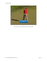
Page 129: ...Evolution Digital EVO SUP DMS2002HD U 001 v1r0 Page 78 Figure 49 DTA On Screen Information Muted Volume Bar ...

Page 130: ...olicy Max Site Errors VCT ID Timezone information including current offset daylight savings entry and exit The timeout policy will dictate what messages the DTA looks for when determining if the timeout counter is decremented Specifically the DTA can either look for a connect or site announcement message Connect and site announcement messages are part of the DTA Operations Messaging Please consult...

Page 131: ...the headend controller Depending on how the site timeout policy was set in the Network Config message the DTA will either look for periodic connect or site announcement messages Please consult with your headend controller manufacture to understand the frequency of the DTA Ops Messages You have reached the end of this document ...

Reviews: