


12
13
Using the
RF output?
SD Setup
Use SD Setup to
scale video to
your TV.
Select SD Setup
and press OK.
The following op-
tions are available;
Aspect Ratio, Just
Scale, Box, and Pan
and Scan.
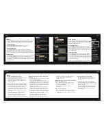
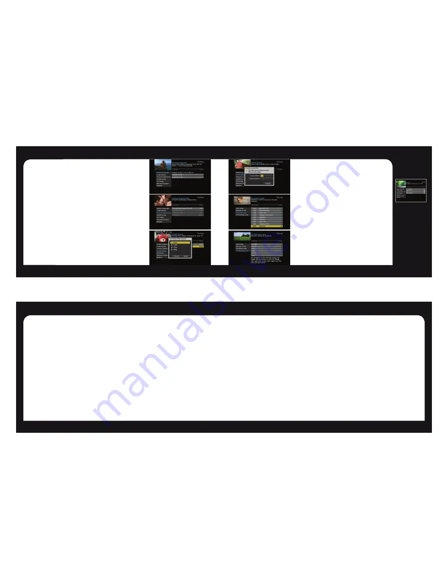
Menu
Menu
Menu
Press the Menu button on your remote control to access the main menu. The menu
will allow you to update your HD set-top box settings. Press the arrow buttons to
navigate through the menu. Press Exit at anytime to return to watching live TV.
Audio Language
è
Select Audio Language, press the OK button on your remote.
Scroll to select the desired Audio Language (if available).
Closed Captioning
è
Select Closed Captioning, press OK to change status from On/Off.
When Closed Captioning is turned On. The following options are available;
Analog Service, Digital Service, Font Size. Scroll through the available settings
using your arrow buttons. Ensure you select Apply to change the CC setting.
HDMI Setup
è
Select TV Aspect Ratio and press the OK button. Select Auto (recommended),
4:3, or 16:9 and press the OK button to select, scroll to Apply and select.
Select TV Output Resolution and press the OK button. Scroll to highlight Auto
(recommended), 1080i, 720p, or 480p and press the OK button to select, scroll
to Apply and select.
Locks Setup
ç
The first time you enter Locks Setup, it will prompt you to
Create Locks PIN. Enter your desired PIN and keep that in a safe
place to refer to later. This PIN will be needed to Change PIN,
Clear PIN and set Channel Locks.
Set Channel Locks
í
Select Channel Locks, a channel list will appear. Scroll up/
down to highlight the channel you would like to lock. Press the
OK button and you will see the unlock icon change to lock. This
will indicate the channel has been locked and will require a PIN
to be entered to view.
TV Ratings Lock
í
Choose TV Ratings Lock to lock programs by their TV Rating.
Use the Arrow (
▲/▼
) buttons to highlight the TV Ratings you
want locked and select OK to lock/unlock the ratings. When you
select a rating it will lock all programs with that rating and higher.
For example if you lock TV-14 it will lock all programs with TV-14
as well as those with TV-MA.
NOTE: Not all programs will have a TV rating and any unrated programs will
never be locked regardless of the TV Ratings Lock selected.
14
15
FAQs
FAQs
powered on and set to the appropriate input source.
Refer to your home theater manual for more
detailed instructions.
Why won’t my HD Set-Top Box respond when I press a
button on the remote control?
• Check the batteries for possible replacement. Refer
to pages 10-11 for more detailed instruction on the
remote control and batteries.
• Refer to page 11 for instructions to pair your
remote control.
What if I forgot my PIN Code?
• Contact your cable provider and they will be able to reset
them back to the default. That will allow you to enter a
new PIN code. Refer to page 13 to learn how to change
your PIN code.
How do I control what my child watches?
• You can restrict viewing of certain material on your
TV in the Locks Setup menu. Refer to page 13
for instructions.
Is it necessary to get a new TV to watch HDTV?
• To view HD channels from your cable provider in their
native resolution, a high-definition “capable” or “ready”
television is required.
• You will also need to use a digital cable connection
such as the HDMI cable to view HD channels. Refer
to the Cable Connections section on page 8 for
more information.
FAQs
Why won’t my HD Set-Top Box turn on?
• Double check that the power cord is connected to the
HD Set-Top Box and the AC wall outlet.
• If the HD Set-Top Box is connected to another unit
(such as a switched outlet or DVD player), verify that
the unit is powered on.
Why do I have no sound when viewing cable channels?
• Verify that the MUTE button on remote control has not
been pressed; try pressing the MUTE button to restore
sound for both the HD Set-Top Box and television.
• Verify that the volume on the HD Set-Top Box is not
turned down. Press the volume up on the Set-Top Box
remote. Volume level will be displayed on the bottom
of the screen.
• Double check your audio connections. Refer to the
Cable Connections section on page 8 to verify
the correct cables are being used for the audio ports. If
they match the diagrams, make sure they are firmly
connected to the ports on both the TV and HD Set-Top Box.
What should I do if there is no video or picture on the
TV screen?
• Try another channel or enter your PIN code, this channel
may be restricted from viewing.
• Verify that your TV is matching the setting on the
HD Set-Top Box. For instance, if you’ve connected using
the coaxial jumper cable, make sure you have the same
channel selected on the TV and 3/4 switch on the back of
the HD Set-Top Box. Refer to Cable Connections section
on page 8 for more details.
• Double check all your cable connections, including
verifying your coaxial cable is securely tightened onto
both the cable wall outlet and the INPUT port of your
HD Set-Top Box. Verify that all video cables between the
HD Set-Top Box and the TV are firmly connected. Refer
to the Cable Connections section on page 8 for more
detailed information regarding the correct
connections and alternative video cable options.
• If the HD Set-Top Box video output is connected to a
home theater unit, verify that the home theater unit is


