www.evolutionsteel.com
7
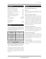
Model EVO230-HDX Specifications
Motor (230v or 115v 50/60 Hz) (Watts)
1750
Maximum Box (1/4” 6mm Wall 900)
84mm
Maximum Box (1/4” 6mm Wall 450)
53mm
Optimum Cutting Thickness (Mild Steel Plate)
12mm
RPM No Load (min
-1
)
2700
Recommended Maximum Duty Cycle 30mins
Sound Pressure Level (Under Load) (dB(A)) 108.7
Vibration Level (Under Load) (m/s2) 3.9
Weight
19.0kg
Maximum Dimensions
370x400x500
Minimum Dimensions
250x325x500
Blade Dimensions
Maximum Diameter
230mm
Bore Diameter
25.4mm
Thickness
2mm
Your Evolution Power Tools saw is shipped complete.
Remove all contents from the box and inspect to ensure
no damage was incurred during shipping, and that the
items listed below are included.
Description
Qty
Instruction Manual
1
Spanner (Attached To Unit)
1
Edge Guide
1
Side Handle
1
Carry Case
1
Batteries
2
GETTING STARTED
CAUTION! ALWAYS DISCONNECT THE SAW FROM
POWER SOURCE BEFORE MAKING ADJUSTMENTS.
Refer to the “Service Parts List Drawing”. If required,
assemble edge guide to shoe plate, and adjust edge guide to
desired position. Secure with thumb screws. Install a blade
as detailed in the “Changing Saw Blades” section. Always
adjust both front and back bevel lock knobs and tighten
before cutting.
What You Should Know Before Sawing:
Warning!
Never start the saw with cutting edge of saw blade contacting
work surface. Do not retract blade guard manually. Guard
retracts automatically.
Mounting / Removing TCT Saw Blades
Remove the chip collection cover from the machine by
undoing the hexagonal screw. Loosen the screw that retains
the spanner to the machine and remove the spanner. Undo
the M13 bolt that secures the blade (fig. 3) and remove the
blade flange. Note: Use spindle lock. Replace blade, making
sure that the arrow for the direction of rotation of the blade
matches that of the machine then tighten the M13 bolt
with the flange in the correct position. Note: Check that the
spindle lock is fully released by manually rotating the blade
before use. Refit the spanner to the holder on the machine
and tighten the retaining screw.
Adjustment Of The Cutting Depth
Release the handle to adjust to the required cutting depth.
Ensure that the blade protrudes a maximum of 3/16” (4mm)
through the material being cut. Tighten the handle to lock in
position. Note: The safety guard (fig. 1) is marked in increments
from 0 – 84mm to assist in setting the depth of cut.
Adjustment Of The Cutting Angle
Release both locking handles (fig. 2) and adjust to the
required cutting angle by lining up the mark with the printed
scale. Tighten both handles to lock in position. Note: There
are certain compound cuts on which it may be necessary to
manually retract the guard to allow the blade to enter into
and / or through the cut.
Line Of Cut Guide Slots
Guide slots are provided at the front of the saw base. The
left slot is used to follow a line when making a 90-degree
cut. The right slot is used to follow a line when making a
45-degree cut.
SPECIFICATIONS
ASSEMBLY
OPERATION


