14
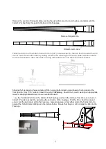
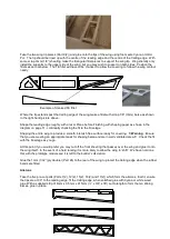
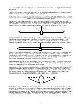
With a pencil mark the centre line of the leading edge and chamfer to a 45° angle with a razor Plane. With a
sharp knife cut slots for four hinges 10mm in from either end and evenly spaced. Ensure that the ailerons sit
flush with the top surface of the wing. Cut 10mm (3/8”) strips from the supplied Mylar hinge material and
insert into the hinge slots, 50% in the Aileron and 50% into the wing.
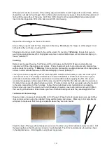
Repeat the above stages for the second aileron.
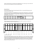
Ensure that you get at least 45° free movement either way.
Do not
glue the hinges in at this stage! Cover
both parts with your chosen covering first.
Shaping to provide a smooth, blemish free surface ready for covering. !!!
Warning
. Ensure that you are
wearing an appropriate mask for shaping balsa and are in well ventilated area, we recommend shaping in
free air (outside).!!!
Covering
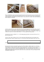
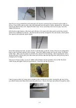
Before covering seat the wing, Tail Plane and Fin and make sure that all fit. Make any alterations as
necessary with Fine shapingpaper and a block. Finally shaping all parts to provide a smooth, blemish free
surface ready for covering. !!!
Warning
. Ensure that you are wearing an appropriate mask for shaping balsa
and are in well ventilated area, we recommend shaping in free air (outside).!!!
This is your chance to express yourself; unlike the ARTF models on the market you can now choose your
own colour scheme. The prototype models were covered in Solarfilm or Profilm, but the choice is yours.
Just make sure that you follow the manufactures recommendations when applying the film. We would
recommend applying a surface sealant to the area around F1 so that the film adheres better in areas where
it is likely to be exposed to glow fuel (glow version). We also recommend that you apply a glow fuel sealant
to the radio compartment of the Fuselage. Follow the manufactures recommendations when applying.
Ensure when you cover the model you do not introduce any warps, cover each section and evenly tighten
the covering on both sides. Ensure when you have Finished covering all parts they are straight and true.
Tail Skid and Undercarriage
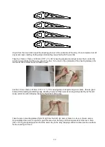
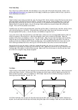
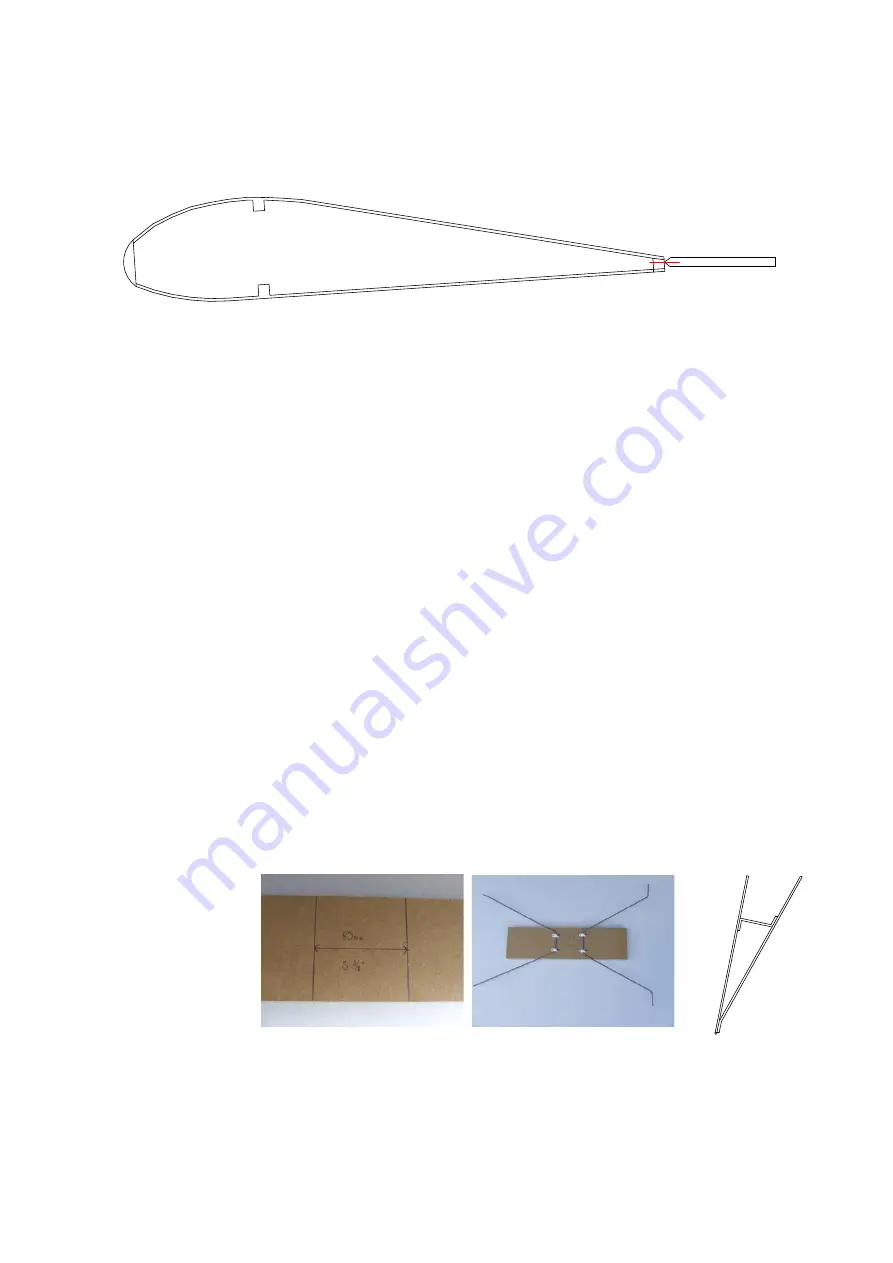
Draw two lines on a piece of scrap ply 85mm (3 3/8”) apart. Place the front leg and rear leg on each of the
lines and screw down using the supplied 10swg saddle clamps and screws. Make any minor adjustments
with pliers to make sure that the legs are parallel where they are to be bound.
Clean the tops of the legs with sand paper or wire wool to remove any dirt or lubricants ready to solder. Pull
the legs together so that they join as shown in the photograph. The U/C should also rake forward as shown
in the diagram below. Bind together using tinned copper wire.


