7
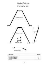
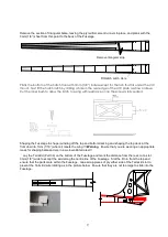
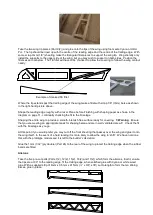
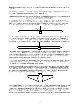
With a sharp knife cut the slots for four hinges 10mm in from either end and evenly spaced, ensure that the
Elevator sits centrally on the Tail Plane. Cut 3/8” (10mm) strips from the supplied Mylar hinge material and
insert into the hinge slots, 50% in the Elevator and 50% into the Tail Plane. Ensure that you get at least 45°
free movement either way.
Do not
glue the hinges in at this stage! Cover both parts with your chosen
covering first.
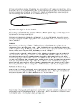
Shaping all parts to a smooth Finish and round off the leading edge of the Tail Plane ready for covering.
!!!
Warning
. Ensure that you are wearing an appropriate mask for shaping balsa and are in a well-ventilated
area. We recommend shaping in free air (outside).!!!
Fuselage
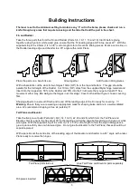
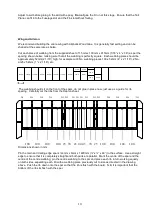
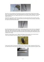
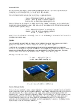
Lay the two Fuselage sides (Parts 1(2) and 2(2)) on the work bench ensuring that you have a left and right
hand side. With a thin layer of epoxy or white wood glue attach the 1mm (1/32”) ply doubler (Part 27(2)).
Weigh down to ensure that the parts cannot ‘curl’ and to allow dry. Glue the reinforcement rails (Part 35 (2))
to the ply doublers, ensuring there is a 3mm gap to allow F1 to fit between the sides
3mm gap for F1
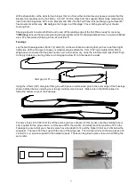
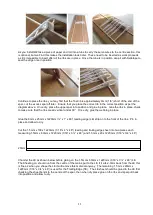
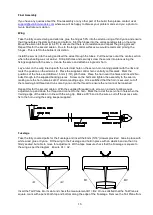
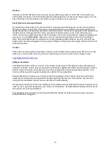
Using the 9.5mm (3/8”) triangular fillet, glue with Cyano or white wood glue to the outer edge of the Fuselage
shown hatched below, including over the ply reinforcement runners. Make cuts in the fillet to allow it to
follow the bottom curve of the Fuselage.
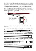
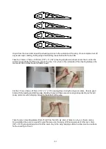
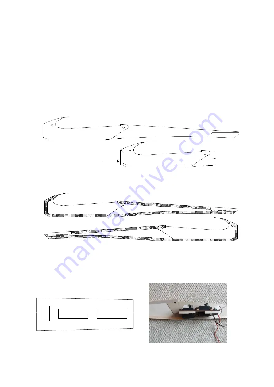
Cut servo holes in F2 (Part 32) to suit the servos you have chosen for this model, note the small 9g hole is
only required for the glow version, cut this area off for the electric. Carefully mark the position of F2 in the
Fuselage to ensure that your chosen servos have the depth to fit, and the higher (front) servo fits below the
wing seat. The rear of F2 lines up with the rear of the wing seat. The front servo sits on the two pieces of 6
x 6mm (¼ x ¼) spruce supplied in the hardware pack. These can be glued in place now or when fitting the
servo later.


