background image

4.   Description of Main Features (fig 2)

 1.  Detergent Hose 

11. Operating Trigger and Safety Catch

 2.  Detergent Hose Connection 

12. Pressure Hose Connection

 3.  Detergent Rate Control 

13. Pressure Regulator

 4.  Drive Engine 

14. Pump Dipstick

 5.  Gearbox Dipstick 

(Depending on Model)


15. Pump Sight Glass

 6.  Gearbox Sight Glass 

(Depending on Model)

  16. Return 

(external return to water supply   

depending on model)

 7.  Hand Lance 

17. Suction Filter

 8.  High/Low Pressure Nozzle 

18. Typical Transport Frame

 9.  High Pressure Hose 

19. Water Inlet

 10. High Pressure Pump 

20. Water Inlet Filter

5.  Installation

5.1   From the pump and gearbox (if fitted) remove the ‘Red’ travel plugs,  


replacing them with the yellow-topped dipsticks. Check all oil levels, top  


up if necessary.

5.2  Fill engine with oil and fuel, see engine manufacturers handbook 


for details of oil and fuel types.

5.3  Connect the battery leads. (Electric start models only).

5.4   Connect the suction hose to the Power Washer (fig 3). Ensure the   


connection has no air leaks. Air leaks on the suction hose connection  


will impair the performance of the machine.

5.5   Connect the water return line to its connector and place the other end in  


the water supply container. (Bypass to tank models only)


(Fig 2 item 16 & Fig 4).

5.6   Submerge the opposite end of the suction hose and its suction filter in a  


suitable container containing the water supply (fig 4). Ensure the filter is  


always kept below the water level.

5.7   Connect the high-pressure hose to the power washer (fig 5) and to the  


lance (fig 6). Tighten as appropriate, do not over tighten. 


Ensure that the trigger safety catch is in the 

ON position

 whilst making


these connections.

Fig 3. Connect the suction hose.

Fig 4. Submerge the suction hose.

Fig 5. Connect the High-Pressure Hose

to the Power Washer.

Fig 6. Connect the High-Pressure

Hose to the Lance.

ALTERNATIVE

VALVE ASSEMBLY

RETURN TO TANK BY-PASS

(Depending on Model)

NOTE

KEEP SUCTION FILTER CLEAN

Return

Suction

Return Hose 

depending on 

model

NOTE:

Typical Example of 

Pressure

Washer Layout

Summary of Contents for GF10150PHR

Page 1: ...CE Operating Instructions 793 1202 Unit 8 Hudson Road Saxby Road Ind Est Melton Mowbray Leicestershire LE13 1BS Telephone 44 0 1664 567226 Fax 44 0 1664 410127 E mail info dualpumps co uk www dualpumps co uk pumps pumps Evolution v pressure washers ...

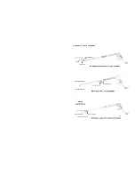
Page 2: ...Appendix 1 Lance variations LOW PRESSURE JET HIGH PRESSURE JET ...

Page 3: ... to be covered by this warranty Warranty claimed items if required urgently will be despatched to the customer and charged for on receipt of the claimed defective item Dual Pumps Ltd will decide whether the claim is valid and if so will issue a credit for the item Should Dual Pumps Ltd find the claimed item to be out of warranty declarations the said charge will stand and be paid by the customer a...

Page 4: ...rature and instructions This warranty shall not apply to any pump or other product which has been repaired or altered to adversely affect the performance or reliability of the pump or product Lance or hoses are not covered by this warranty due to the adverse conditions of their use Neither this warranty nor any implied warranty apply to damage caused by any of the following 1 Freight damage 2 Fros...

Page 5: ...Level for this equipment Part No Engine Lpm Bar Kg L x W x H SPL LwA dB GSPL LwA dB GF10150PHR Petrol GP160 10 150 31 600x450x440 107 111 GF13150PHR Petrol GP200 13 150 31 600x450x440 106 111 GT10150PHR Petrol GP160 10 150 36 940x600x890 107 111 GT13150PHR Petrol GP200 13 150 37 940x600x890 106 111 E1F10135PHR Petrol GX120 10 135 31 2 600x450x440 98 111 E1C12150PHR Petrol GX160 12 150 35 5 600x400...

Page 6: ...lear and free from obstructions consideration should be given to the erection of fences or sheeting to prevent injury to others High pressure lances react Kick Back when the operating trigger is pulled Ensure you have a good firm footing and anticipate this reaction Extra care should be taken when working at heights scaffolding should be in good condition secure and properly fenced working from la...

Page 7: ...ons 2005 This machine in its standard form dose not exceed the 2 5 m s vibration action value and should not require any daily limitations to it use Periodic equipment checks and servicing will maintain the characteristics and efficiency of this machine Warning Any modifications or accessories added or use with this machine may affect the vibration levels Under the Control of Vibration at Work Reg...

Page 8: ...nnect the suction hose to the Power Washer fig 3 Ensure the connection has no air leaks Air leaks on the suction hose connection will impair the performance of the machine 5 5 Connect the water return line to its connector and place the other end in the water supply container Bypass to tank models only Fig 2 item 16 Fig 4 5 6 Submerge the opposite end of the suction hose and its suction filter in ...

Reviews: