background image

15

www.evolutionpowertools.com

IT

FR

EN

NL

OPERATION

GETTING STARTED

CAUTION! ALWAYS DISCONNECT THE SAW FROM THE 
POWER SOURCE BEFORE MAKING ANY ADJUSTMENTS.

Refer to the “Service Parts List Drawing”. Install a blade as 
detailed in the “Installing or Removing the Blade” section. 

1. Mounting the Table Mitre Saw

WARNING: 

To reduce the risk of injury from unexpected saw 

movement, place the saw in the desired location either on a 
workbench or other recommended leg set. The base of the saw 
has four holes to mount the mitre saw. If the saw is to be used in 
one location, permanently fasten it to the workbench or leg set 
using appropriate bolts with lock washers and nuts.

• 

Tighten the mitre and bevel locks.

• 

Position the saw so other people cannot stand behind it. 
Thrown debris could injure people in its path.

• 

Place the saw on a firm, level surface where there is plenty of 
room for handling and properly supporting the workpiece.

• 

Support the saw so that the table is level and the saw does 
not rock.

• 

Bolt or clamp the saw to its support.

2. Installing or Removing the Blade

WARNING:

 Only use genuine Evolution blades which are 

designed for this machine. Ensure that the maximum speed 
of the blade is compatible with the machine. Only perform 
this operation with the machine disconnected from the mains 
supply.

Note:

 It is recommended that the operator considers wearing 

protective gloves when handling the blade during installation 
or when changing the machines blade.

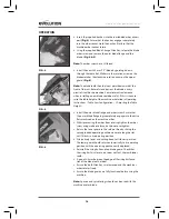
• 

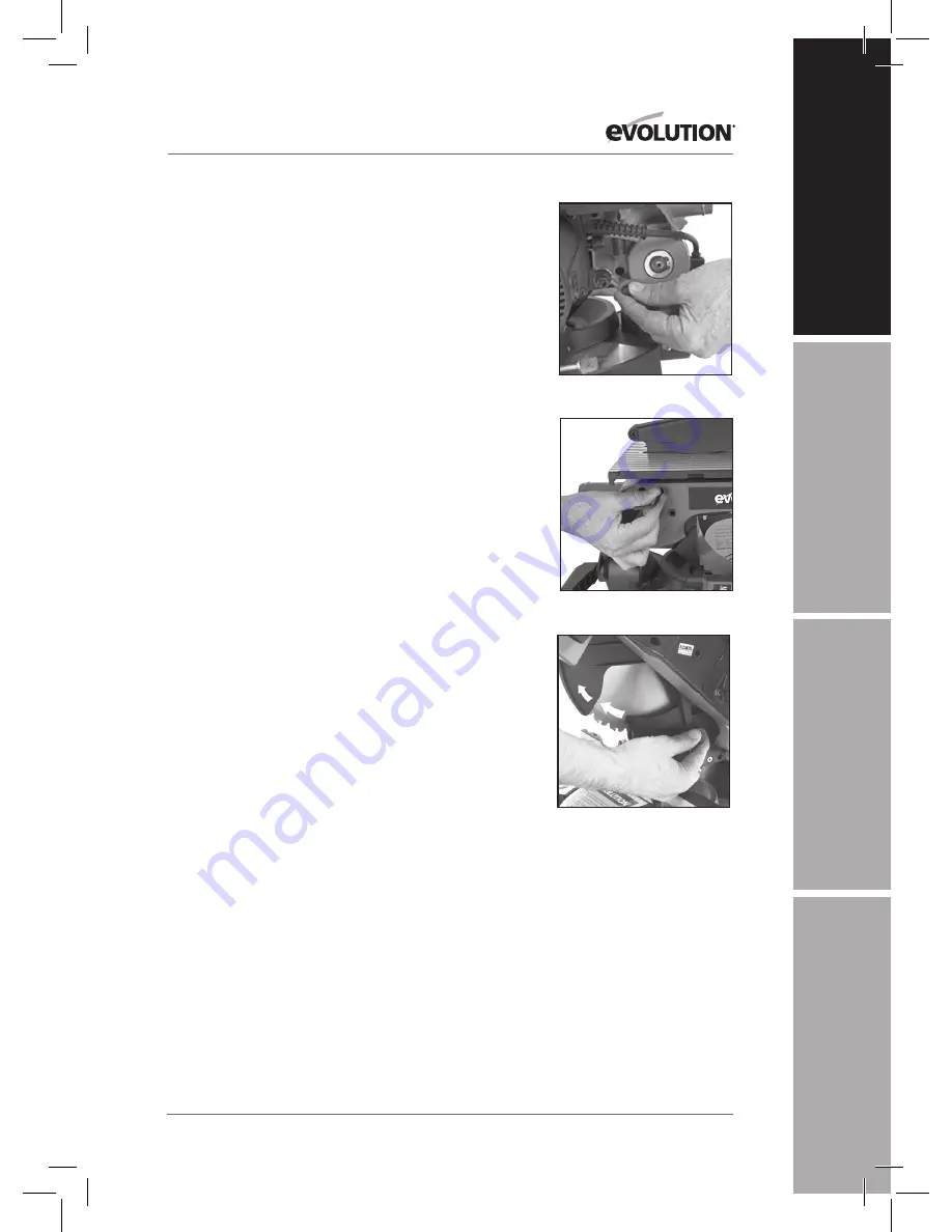
Pull out the cutting head locking pin and allow the cutting 
head to rise to its upper position.

 (Fig. 1)

• 

Remove the top blade guard with the attached riving knife 
by loosening the socket headed fixing screw 

(Fig. 2)

 and 

withdrawing the riving knife upwards. The riving knife is 
slotted for easy removal.

• 

Push in the sprung loaded lower guard operating pawl and 
slide it upwards along the slot. The lower guard will rotate 
into the machine exposing the blade.  

(Fig.  3) 


FIG. 1

FIG. 2

FIG. 3

Summary of Contents for RAGE 6

Page 1: ...Date Published 01 03 2016 Written in UK English RAGE 6 Original Instructions IT FR EN NL...

Page 2: ......

Page 3: ...ENGLISH Original Instructions NL...

Page 4: ...ge 5 Warranty Page 5 Specification Page 6 Labels Symbols Page 7 General Safety Rules Page 8 Additional Specific Safety Rules Page 9 Machine Overview Page 12 Service Parts Diagram Page 14 Operation Mit...

Page 5: ...will within the guarantee period and from the original date of purchase repair or replace any goods found to be defective in materials or workmanship This guarantee is void if the tool being returned...

Page 6: ...Mitre x 90 Bevel 150 x 70mm 5 7 8 x 2 3 4 Wood 45 Mitre x 45 Bevel 50 x 50mm 2 x 2 table saw MODE Maximum cutting Mild Steel 6mm 1 4 Wood 40mm 1 1 2 Table Dimensions 570 x 450mm 22 1 2 x 17 3 4 Blade...

Page 7: ...standard test method and may be used for comparing one tool with another The declared vibration total value may also be used in a preliminary assessment of exposure WARNING The vibration emission duri...

Page 8: ...the rate for which they were intended 7 Use the right tool Do not force small tools to do the job of a heavy duty tool Do not use tools for purposes not intended for example do not use circular saws t...

Page 9: ...g with and to reduce the risk of exposure You should Work in a well ventilated area Work with approved safety equipment such as dust masks that are specially designed to filter microscopic particles A...

Page 10: ...hen sawing long work pieces always use extra support to provide better support and use clamps or other clamping devices To reduce the risk of injury return the slide carriage to the full rear position...

Page 11: ...own the head using the head locking pin Loosen the mitre angle lock knob Push down the mitre angle lever and rotate the table to either of its maximum settings Lock the table in position using the loc...

Page 12: ...off trigger switch 2 Cutting head locking pin 3 Cutting handle 4 Rotary table 5 Lower blade guard 6 Upper blade guard 7 Blade 8 Mitre lock knob 9 Bevel angle locking lever 10 Mitre angle scale 11 Posi...

Page 13: ...IT FR EN NL OVERALL VIEW OF RAGE 6 IN TABLE SAW CONFIGURATION Know your parts 1 On off trigger switch 2 Cutting handle 3 Table top 4 Auxilliary lower blade guard 5 Upper blade guard 6 Blade 7 Rip fenc...

Page 14: ...14 www evolutionpowertools com PARTS DIAGRAM Parts Diagrams can also be downloaded from www evolutionpowertools com...

Page 15: ...oom for handling and properly supporting the workpiece Support the saw so that the table is level and the saw does not rock Bolt or clamp the saw to its support 2 Installing or Removing the Blade WARN...

Page 16: ...figuration 2 Adjusting the Table Height Install the outer blade flange and arbor screw Ensure that the outer blade flange lugs completely engage into the drive flats machined on the machine arbor Whil...

Page 17: ...the collection bag should be removed and replaced with a blanking plug not supplied Reinstate the dust bag when cutting wood 4 Fitting the Hold Down Clamp Fig 7 Two sockets one either side are incorp...

Page 18: ...ed to the riving knife using the sprung loaded locating pin The table should be adjusted so that it is in its upper most position See section 2 Table Saw Configuration for adjusting procedure In this...

Page 19: ...elease thumb button on the top of the saw handle Fig 10 Gently lower the cutting head through the workpiece to make a cut To switch Off Allow the cutiing head to rise to its upper position Release the...

Page 20: ...tting head can be set at any angle up to a 45 to the LH side only The bevel angle locking lever is found at the rear of the machine and a protractor guide and pointer is incorporated into the casting...

Page 21: ...ocking screw The cutting head should be locked at 0 bevel with the bevel locking lever securely tightened The auxiliary lower blade guard must be fitted Note Ensure that these checks adjustments are c...

Page 22: ...wise or counter clockwise until the saw blade protrudes through the table by the required amount Tighten the two table pillar wing nuts securely Note The upper blade guard can be rotated backwards to...

Page 23: ...fence carrier in a Hi and a Lo position The normal and factory supplied position is with the fence set to the Hi setting The Lo setting can be useful when cutting very thin sheet material To re posit...

Page 24: ...ould always be done with the Rip Fence set to the desired width and on the RH side of the machines table Note Check that the rip fence is locked in position and is parallel to the saw blade Check that...

Page 25: ...The riving knife is a very important component and comes factory fitted and correctly aligned and adjusted The riving knife prevents the work from binding as it passes through the blade Inspect the r...

Page 26: ...re not supplied to check that the angle between the machines fence guide and the blade is 90 Fig 24 If the angle requires adjustment loosen the four fence guide clamp screws and align the fence guide...

Page 27: ...ollowing code Blue Neutral Brown Live Green Yellow Earth The wire that is coloured blue must be connected to the terminal that is marked with the letter N The wire that is coloured brown must be conne...

Page 28: ...ity Directive 93 68 EC The CE Marking Directive 2011 65 EU The Restriction of the Use of certain Hazardous Substances in Electrical Equipment RoHS Directive 2002 96 EC as The Waste Electrical and Elec...

Page 29: ...29 www evolutionpowertools com IT FR EN NL NOTES...

Page 30: ...30...

Page 31: ...31 IT FR EN NL FRAN AIS Traduction de manuels d instruction d origine...

Page 32: ...ns Page 34 tiquettes et symboles Page 35 R gles de s curit g n rales Page 35 R gles de s curit particuli res suppl mentaires Page 38 Pr sentation de l appareil Page 42 Sch ma des pi ces de rechange Pa...

Page 33: ...s sera dans la p riode de garantie et partir de la date d achat originale r parer ou remplacer tout produit reconnu d fectueux dans les mat riaux ou de fabrication Cette garantie est nulle si l outil...

Page 34: ...70mm 5 7 8 x 2 3 4 Bois 45 x 45 Mitre Bevel 50 x 50mm 2 x 2 scie MODE coupe maximale Acier Doux 6mm 1 4 Bois 40mm 1 1 2 Dimensions De La Table 570 x 450mm 22 1 2 x 17 3 4 LAME Diam tre 255mm 10 Nombre...

Page 35: ...est standard et peut tre utilis e pour comparer un outil un autre La valeur totale des vibrations d clar e peut galement tre utilis e lors d une valuation pr liminaire d exposition AVERTISSEMENT L mis...

Page 36: ...ais les outils pr s de liquides ou de gaz inflammables 3 Prot gez vous contre les lectrocutions vitez tout contact du corps avec des surfaces mises la terre 4 Tenez les autres personnes loign es Ne la...

Page 37: ...l outil est utilis l ext rieur utilisez uniquement des rallonges sp ciales usage ext rieur et tiquet es comme telles 19 Restez sur vos gardes Concentrez vous sur ce que vous tes en train de faire res...

Page 38: ...rter ou autres pi ces endommag es devraient tre soigneusement v rifi es afin de d terminer si elles fonctionneront correctement et ex cuteront la fonction pour laquelle elles ont t con ues V rifiez qu...

Page 39: ...tilisation de la machine 20 clairez votre espace de travail ou zone de travail imm diate de mani re ad quate 21 Lorsqu elle est pourvue d un laser aucun change avec un type de laser diff rent n est au...

Page 40: ...t du biseau sur le carter afin d viter tout mouvement soudain 5 Verrouillez la t te de coupe le plus bas possible Veillez ce que la broche de fixation de la t te de coupe soit compl tement enclench e...

Page 41: ...Accessoires compl mentaires En plus des accessoires standards fournis avec cette machine d autres accessoires sont disponibles pour am liorer ses performances ceux ci incluent les articles suivants 1...

Page 42: ...rouillage de la t te de coupe 3 Poign e de d coupe 4 Table tournante 5 Carter de lame inf rieur 6 Carter de lame sup rieur 7 Lame 8 Bouton de verrouillage de l onglet 9 Levier de verrouillage de l ang...

Page 43: ...FIGURATION DE LA SCIE ONGLETS RAGE 6 Pi ces de la scie circulaire d tabli 1 Interrupteur g chette marche arr t 2 Poign e de d coupe 3 Haut de la table 4 Carter de lame inf rieur auxiliaire 5 Carter de...

Page 44: ...44 www evolutionpowertools com SCH MA DES PI CES DE RECHANGE...

Page 45: ...un endroit o il y a suffisamment d espace pour manipuler et supporter de mani re appropri e la pi ce usiner Soutenez la scie afin que la table soit niveau et que la scie ne tangue pas Boulonnez ou se...

Page 46: ...re table 2 Ajustement de la hauteur de la table Installez la bride de lame ext rieure et la vis de l arbre Veillez ce que les oreilles de la bride de lame ext rieure s enclenchent compl tement dans le...

Page 47: ...devrait tre retir et remplac par un bouchon obturateur non fourni Remontez le sac poussi re lorsque vous d coupez du bois 4 Installation de la pince de verrouillage Fig 7 Deux douilles une de chaque c...

Page 48: ...sort La table devrait tre ajust e afin qu elle soit dans la position la plus haute Voir la section 2 Configuration de la scie circulaire table pour conna tre la proc dure d ajustement Dans cette posit...

Page 49: ...chement de la t te en haut de la poign e de la scie Fig 10 Abaissez doucement la t te de coupe travers la pi ce usiner pour la d couper Pour mettre sur Arr t Laissez la t te de coupe se relever son ma...

Page 50: ...te de coupe peut tre r gl e un angle allant jusqu 45 du c t gauche uniquement Le levier de verrouillage de l angle du biseau se trouve l arri re de la machine et un guide gradu et un pointeur sont inc...

Page 51: ...ge de l onglet La t te de coupe devrait tre verrouill e au biseau 0 avec le levier de verrouillage du biseau bien serr Le carter de lame inf rieur auxiliaire doit tre install Remarque Veillez ce que c...

Page 52: ...dans le sens contraire des aiguilles d une montre jusqu ce que la lame de la scie d passe de la table de la longueur requise Serrez bien les deux crous ailettes de la colonne de la table Remarque Le...

Page 53: ...normale et d usine fournie est avec le guide r gl sur Haut Le r glage Bas peut tre utile lors de la d coupe de feuilles tr s fines Pour repositionner le guide de refend sur le r glage Bas Desserrez l...

Page 54: ...ent 2 D coupe longitudinale La d coupe longitudinale se fait sur la longueur d une pi ce plut t qu en travers La d coupe longitudinale devrait toujours tre effectu e avec le guide de refend r gl la la...

Page 55: ...couteau fendeur est un composant tr s important et est install en usine et correctement align et ajust Le couteau fendeur pr vient contre une flexion du travail mesure qu il passe travers la lame Ins...

Page 56: ...lame soit de 90 Fig 24 Si l angle doit tre ajust desserrez les quatre vis de fixation du guide et alignez le guide de refend contre l querre d ing nieur Resserrez les vis de fixation De m me v rifiez...

Page 57: ...ques sont color s suivant le code ci dessous Bleu Neutre Brun Sous tension Vert Jaune Terre Le fil color en bleu doit tre branch la borne marqu e de la lettre N Le fil color en brun doit tre branch la...

Page 58: ...e relative au marquage CE 2011 65 EU Directive relative la limitation de l utilisation de certaines substances dangereuses dans les quipements lectriques et lectroniques RoHS 2002 96 EC Telle que modi...

Page 59: ...59 www evolutionpowertools com IT FR EN NL Remarques...

Page 60: ...60...

Page 61: ...61 italiano Traduzione di manuali di istruzioni originali...

Page 62: ...Page 65 Regole generali di sicurezza Page 66 Dettagli di sicurezza supplementari Page 68 Panoramica dello strumento Page 72 Schema componenti per riparazioni Page 74 Istruzioni Sul Funzionamento Conf...

Page 63: ...n Power Tools entro i garantire periodo e dalla data originale di acquistare riparare o sostituire le merci che difetti di materiale o di lavorazione questo garanzia nulla se lo strumento viene restit...

Page 64: ...150 x 70mm 5 7 8 x 2 3 4 Legno 45 x 45 Mitre Bevel 50 x 50mm 2 x 2 sega MODE ditaglio massima Acciaio Dolce 6mm 1 4 Legno 40mm 1 1 2 Tabella Dimensioni 570 x 450mm 22 1 2 x 17 3 4 LAMA Diametro 255mm...

Page 65: ...ire dal valore complessivo dichiarato in base al modo in cui lo strumento utilizzato La necessit di identificare le misure di sicurezza e proteggere l operatore si basa sulla valutazione dell esposizi...

Page 66: ...nati Mantenere l area di lavoro ben illuminata Non utilizzare mai gli utensili vicino a liquidi o gas infiammabili 3 Proteggersi dalle scosse elettriche Evitare il contatto del corpo con superfici mes...

Page 67: ...izzato in ambienti esterni utilizzare soltanto delle prolunghe progettate per uso esterno ed etichettate come tali 19 Restare vigili Concentrarsi su ci che si sta facendo utilizzare il buon senso e no...

Page 68: ...re utilizzo dello strumento il coprilama o ogni altra parte danneggiata deve essere controllata con attenzione per determinarne il corretto funzionamento e che essa svolga la funzione desiderata Verif...

Page 69: ...one adeguata l ambiente di lavoro o la zona di lavoro adiacente 21 Se installata una guida laser utilizzare soltanto parti originali Evolution per riparare o sostituire il laser Le riparazioni devono...

Page 70: ...e lo strumento tramite il cavo dell alimentazione potrebbe danneggiare l isolamento o i collegamenti dei cavi provocando scosse elettriche o incendi 4 Prima di spostare la sega stringere la manopola d...

Page 71: ...inferiore 1 Ulteriori accessori Oltre all attrezzatura standard fornita con questa macchina sono disponibili altri accessori presso il vostro rivenditore o contattando Evolution Power Tools Essi inclu...

Page 72: ...ore grilletto on off 2 Perno di blocco leva di taglio 3 Maniglia di taglio 4 Tavolo rotante 5 Coprilama inferiore 6 Coprilama superiore 7 Lama 8 Leva blocco angolare 9 Manopoladibloccoangolazione 10 S...

Page 73: ...I RAGE 6 NELLA CONFIGURAZIONE DI SEGA DA BANCO Conoscere le proprie parti 1 Interruttore grilletto on off 2 Maniglia di taglio 3 Parte superiore tavolo 4 Coprilama inferiore 5 Coprilama superiore 6 La...

Page 74: ...74 www evolutionpowertools com SCHEMA COMPONENTI PER RIPARAZIONI...

Page 75: ...una superficie piana e stabile dove ci sia abbastanza spazio per maneggiarla e un sostegno adeguato per l oggetto di lavoro Sostenere la sega in modo che il tavolo sia in piano e la sega non oscilli A...

Page 76: ...altezza banco Installare la flangia esterna della lama e la vite dell albero Assicurarsi che la flangia esterna della lama sia completamente inserita negli alloggiamenti di guida presenti sull albero...

Page 77: ...to di raccolta deve essere rimosso e sostituito con un tappo di chiusura non fornito Installare di nuovo il sacchetto quando si taglia il legno 4 Installare il dispositivo di fissaggio Fig 7 Due fori...

Page 78: ...re utilizzando il perno di posizionamento a molla Il banco deve essere regolato in modo che sia nella sua posizione pi elevata Vedere sezione 2 configurazione della sega da banco per la procedura di r...

Page 79: ...ama inferiore e la testa di taglio premere il pulsante di rilascio della testa sulla parte superiore del manico della sega Fig 10 Abbassare delicatamente la testa di taglio attraverso l oggetto di lav...

Page 80: ...golazione fino a 450 soltanto sul lato sinistro La leva di blocco dell angolo di bisellatura si trova sul retro della macchina e una guida goniometrica e un puntatore sono incorporati nella parte fron...

Page 81: ...di taglio deve essere in posizione di blocco verso il basso con il perno di blocco completamente inserito nella sua base Il tavolo rotante deve essere impostato a 00 e bloccato in posizione con la vi...

Page 82: ...di regolazione dell altezza Fig 18 in senso orario o antiorario fino a quando la lama della sega non sporge dalla tavola quanto si desidera Avvitare saldamente i due dadi a farfalla del tavolo Nota Il...

Page 83: ...rrello in posizione alta Hi e bassa Low La posizione fornite dalla fabbrica e normale quella in configurazione alta L impostazione bassa pu essere utile durante il taglio di materiale in fogli estrema...

Page 84: ...a parallela impostata sulla larghezza desiderata e sul lato destro del tavolo della macchina Nota Controllare che la guida parallela sia bloccata in posizione e sia parallela alla lama della sega Cont...

Page 85: ...lire le parti in plastica Pulire soltanto con un panno morbido leggermente umido Coltello divisore Il coltello divisore un componente molto importante ed installato in fabbrica e correttamente allinea...

Page 86: ...sellata non fornita per controllare che l angolo tra la guida della macchina e la lama sia di 900 Fig 24 Se l angolo richiede una regolazione allentare le quattro viti di fissaggio della guida e allin...

Page 87: ...L TUTELA DELL AMBIENTE Lo smaltimento dei prodotti elettrici non deve essere effettuato con i rifiuti domestici Si prega di riciclare nelle strutture preposte Consultare la propria autorit locale o il...

Page 88: ...it elettromagnetica 93 68 EC La direttiva sul marchio CE 2011 65 EU La restrizione dell uso di determinate sostanze pericolose Sostanze nelle apparecchiature elettriche RoHS 2002 96 EC La direttiva su...

Page 89: ...89 www evolutionpowertools com IT FR EN NL Appunti...

Page 90: ......

Page 91: ...Nederlands Vertaling van de originele gebruiksaanwijzing...

Page 92: ...Specificatie Page 94 Labels en symbolen Page 95 Algemene veiligheidsregels Page 96 Aanvullende specifieke veiligheidsinstructies Page 98 Machine overzicht Page 102 Schema van serviceonderdelen Page 10...

Page 93: ...van aankoop reparatie of enige goederen defect in materialen of vakmanschap te vervangen Deze garantie vervalt als het instrument wordt teruggegeven is gebruikt dan de aanbevelingen in de handleiding...

Page 94: ...e x 90 Bevel 150 x 70mm 5 7 8 x 2 3 4 Hout 45 Mitre x 45 Bevel 50 x 50mm 2 x 2 tafelcirkelzaag MODE Maximale snij Mild Steel 6mm 1 4 Hout 40mm 1 1 2 Tafel Afmetingen 570 x 450mm 22 1 2 x 17 3 4 mes Di...

Page 95: ...emissie tijdens werkelijk gebruik van het elektrische gereedschap kan verschillen met de vermelde totaalwaarde afhankelijk van de manieren waarop het gereedschap wordt gebruikt De noodzaak veiligheids...

Page 96: ...natte locaties Zorg dat de werkplek goed is verlicht Gebruik geen gereedschap in aanwezigheid van brandbare vloeistoffen of gassen 3 Pasopvoorelektrischeschok Vermijd contact van het lichaam met geaar...

Page 97: ...n gebruiken die bestemd zijn voor gebruik buitenshuis en als zodanig zijn gemarkeerd 919 Blijf alert Let op wat u doet gebruik uw gezonde verstand en gebruik het gereedschap niet wanneer u moe bent 20...

Page 98: ...op verkeerde uitlijning of vastlopen van bewegende onderdelen breuk van onderdelen en elke andere conditie die van invloed kan zijn op de werking van het gereedschap Een beschadigde beschermkap of and...

Page 99: ...enlaser alleen echteonderdelenvanEvolutiongebruiken voorreparatieofvervangingvandelaser Reparaties dienen alleen te worden uitgevoerd door de fabrikant van de laser of een bevoegde agent 22 Verwijder...

Page 100: ...dvat Door de machine aan het snoer te dragen kan schade ontstaan aan de isolatie of de draadaansluitingen hetgeen kan resulteren in elektrische schok of brand 4 Draai alvorens de zaag te verplaatsen d...

Page 101: ...voor het onderste blad 1 Aanvullende accessoires Naast de met deze machine meegeleverde standaard apparatuur zijn andere accessoires verkrijgbaar bij uw plaatselijke leverancier Deze omvatten de volge...

Page 102: ...Zaagkopborgpen 3 Zaaghendel 4 Draaitafel 5 Onderste bladbeschermkap 6 Bovenste bladbeschermkap 7 Blad 8 Schuinteborghendel 9 Verstekhoekborgknop 10 Verstekhoekschaal 11 Positieve stopborghendel 12 Gel...

Page 103: ...evolutionpowertools com IT FR EN NL MACHINE OVERZICHT 1 Aan uit schakelaar 2 Zaaghendel 3 Tafelblad 4 Onderste hulpbladbeschermkap 5 Bovenste bladbeschermkap 6 Blad 7 Schulpgeleider 8 Duwstok 8 5 3 7...

Page 104: ...104 www evolutionpowertools com SCHEMA COMPONENTI PER RIPARAZIONI...

Page 105: ...ing en correcte ondersteuning voor het werkstuk Ondersteun de zaag zodanig dat hij horizontaal is en de zaag niet schommelt Zet de zaag met bouten of klemmen vast op zijn ondersteuning 2 Installeren o...

Page 106: ...buitenste bladflens en doornschroef Controleer of de buitenste bladflenslipjes volledig pakken in de drijfvlakken die machinaal worden bewerkt op de opspandoorn van de machine Terwijl wordt voorkomen...

Page 107: ...rden verwijderd en vervangen door een afsluitplug niet meegeleverd Zet de stofzak terug bij het zagen van hout 4 Monteren van de vasthoudklem Fig 7 Er zijn twee holtes aangebracht een aan elke zijde i...

Page 108: ...ard voor toekomstig gebruik De bovenste bladbeschermkap moet worden vastgezet aan het spouwmes met behulp van de geveerde bevestigingspen De tafel dient zodanig te worden aangepast dat hij in zijn hoo...

Page 109: ...n van de kop boven op het zaaghandvat drukken Fig 10 Breng de zaagkop voorzichtig omlaag door het werkstuk om een zaagsnede te maken Uit schakelen Laat de zaagkop omhoog komen naar zijn hoogste stand...

Page 110: ...de linkerkant in elke hoek worden ingesteld tot 45o De borghendel van de schuine hoek kunt u vinden aan de achterkant van de machine en een hoekmetergeleider en wijzer zijn opgenomen in de kast aan d...

Page 111: ...De zaagkop moet in de geborgde lage stand staan met de borgpen volledig in zijn opening gestoken De draaitafel dient te worden ingesteld op 0o en in die stand worden vastgezet met de verstekborgschro...

Page 112: ...onder de machinetafel Fig 17 Draai de hoogteafstellingsschroef Fig 18 naar rechts of naar links tot het zaagblad met de gewenste hoeveelheid door de tafel uitsteekt Draai de twee vleugelmoeren van de...

Page 113: ...en een Lage stand De normale en door de fabriek geleverde stand is met de geleider ingesteld op de Hoge instelling De Lage instelling kan nuttig zijn bij het zagen van zeer dun plaatmateriaal Voor het...

Page 114: ...lpgeleider ingesteld op de gewenste breedte en aan de rechterkant van de tafel van de machine N B Controleer of de schulpgeleider op zijn plaats is vastgezet en parallel is aan het zaagblad Controleer...

Page 115: ...ar zij kunnen worden beschadigd door oplosmiddelen Reinig alleen met een zachte iets vochtig gemaakte doek Spouwmes Het spouwmes is een zeer belangrijke component en wordt in de fabriek gemonteerd en...

Page 116: ...verd om te controleren of de hoek tussen de machinegeleider en het blad 90o is Fig 24 Draai wanneer de hoek afgesteld moet worden de vier geleiderklemschroeven los en breng de geleider in lijn met de...

Page 117: ...IT FR EN NL MILIEUBESCHERMING Elektrische afvalproducten dienen niet te worden weggegooid met het huisvuil Recycle waar voorzieningen aanwezig zijn Vraag uw gemeentelijke instantie of verkoper om advi...

Page 118: ...elektromagnetische compatibiliteit 93 68 EC De CE merk richtlijn 2011 65 EU De richtlijn Beperking van het gebruik van bepaalde gevaarlijke stoffen in elektrische apparatuur RoHS 2002 96 EC De richtl...

Page 119: ...119 www evolutionpowertools com IT FR EN NL aantekeningen...

Page 120: ...the QR code Right UK Evolution Power Tools Ltd Venture One Longacre Close Holbrook Industrial Estate Sheffield S20 3FR 44 0 114 251 1022 US Evolution Power Tools LLC 8363 Research Drive Davenport Iowa...

Reviews: