background image

INSTALLATION AND CONFIGURATION MANUAL 

DIO88 


Table of Contents                              


Table of Contents 

2


Introduction to Synapse 

3


An Introduction to Synapse 

3


Local Control Panel 

3


Remote Control Capabilities 

3


Unpacking and Placement 

4


Unpacking 

4


Locating the card 

4


A Quick Start 

5


When Powering-up 

5


Default settings 

5


Changing settings and parameters 

5


Front Panel Control 

5


Example of changing parameters using front panel control 

6


EVS Cortex 

7


Menu Structure Example 

7


The DIO88 Card 

8


Introduction 

8


Applications 

8


Program Procedure 

8


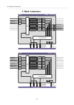
Block schematics 

9


Settings Menu 

11


Introduction 

11


SRC 

11


In_Out 

11


Sel_Ch1 ~ Sel_Ch16 

11


Ch_1 ~ Ch_16 

11


Gain-CH_1 ~ 

12


Gain-CH_16 

12


Phase-CH_1 ~ Phase-CH_16 

12


Stereo-CH_1/2 ~ Stereo-CH_15/16 

12


Delay_CH_1/2 ~ Delay_CH_15/16 

12


Slot1/2 ~ Slot31/32 

12


Status Menu 

13


Introduction 

13


Addon-lock 

13


AES-In_1 ~ 

13


AES-In_8 

13


Ch_1_Inp ~ Ch_16_Inp 

13


Events Menu 

14


Introduction 

14


What is the Goal of an event? 

14


DIO88 Events 

14


Announcements 

14


Audio-Data 

14


Reference 

14


What information is available in an event? 

14


The Message String 

14


The Tag 

15


Defining Tags 

15


The Priority 

15


The Address 

15


LED Indication 

16


ERROR 

16


INPUT 1 ~ 

16


INPUT 8 

16


REFERENCE 

16


DATA ERROR 

16


CONNECTION 

16


Block Schematics 

17


Connector Panel 

19


Appendix 1 

20


Quad speed ADD-ON bus 

20


Scope 

20


Features 

20


Example 

21


Multiplexing 

22


Summary of Contents for SYNAPSE DIO88

Page 1: ...INSTALLATION CONFIGURATION MANUAL DIO88 UNIVERSAL TRIPLE MODE 16 CHANNEL AUDIO I O CARD FOR QUAD SPEED ADD ON APPLICATIONS ...

Page 2: ...he user documentation Do not hesitate to send improvement requests or report any error or inaccuracy on this user manual by e mail to doc evs com Regional Contacts The address and phone number of the EVS headquarters are usually mentioned in the Help About menu in the user interface You will find the full list of addresses and phone numbers of local offices either at the end of this user manual fo...

Page 3: ... product to extremely high or low temperatures NEVER operate this product in an explosive atmosphere Warranty EVS warrants their products according to the warranty policy as described in the general terms That means that EVS Broadcast Equipment SA can only warrant the products as long as the serial numbers are not removed Copyright 2001 2021 EVS Broadcast Equipment SA Date created 29 06 2010 Date ...

Page 4: ... Introduction 11 SRC 11 In_Out 11 Sel_Ch1 Sel_Ch16 11 Ch_1 Ch_16 11 Gain CH_1 12 Gain CH_16 12 Phase CH_1 Phase CH_16 12 Stereo CH_1 2 Stereo CH_15 16 12 Delay_CH_1 2 Delay_CH_15 16 12 Slot1 2 Slot31 32 12 Status Menu 13 Introduction 13 Addon lock 13 AES In_1 13 AES In_8 13 Ch_1_Inp Ch_16_Inp 13 Events Menu 14 Introduction 14 What is the Goal of an event 14 DIO88 Events 14 Announcements 14 Audio D...

Page 5: ...troller The local control panel is also used to back up and restore card settings Please refer to the RRC18 RRC10 RRC04 RRS18 and RRS04 manuals for a detailed description of the local control panel the way to set up remote control over IP and for frame related settings and status information Remote Control Capabilities The remote control options are explained in the rack controller RRC18 RRC10 RRC...

Page 6: ...llowed will prevent premature failure from components mounted on the board Locating the card The Synapse card can be placed vertically in an SFR18 frame or horizontally in an SFR08 or SFR04 frame Locate the two guide slots to be used slide in the mounted circuit board and push it firmly to locate the connectors Correct insertion of card is essential as a card that is not located properly may show ...

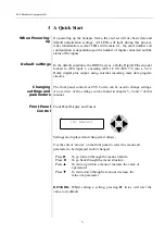
Page 7: ...ng external incoming meta data program streams Changing settings and parameters The front panel controls or EVS Cortex can be used to change settings An overview of the settings can be found in chapter 5 6 and 7 of this manual Front Panel Control Front Panel Display and Cursor Settings are displayed and changed as follows Use the cursor arrows on the front panel to select the menu and parameter to...

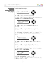
Page 8: ...ts The display changes to indicate that the SFS10 Settings menu item SDI Format has been selected and shows that it current setting is Auto Pressing the selects the settings item shown in this example SDI Format Pressing or will change to a different setting eg Mode H Delay The display changes to indicate that the SFS10 Edit Setting menu item SDI Format has been selected To edit the setting of the...

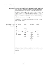
Page 9: ... EVS Cortex has access to data contained within the Synapse module and displays it on a GUI The software has an intuitive structure following that of the module that it is controlling For operation of EVS Cortex please refer to the EVS Cortex help files press F1 in any window Menu Structure Example Slot Module Item Parameter Setting S02 Identity S0 1 SFS10 Setti ngs SDI Format Auto S00 RRC18 Statu...

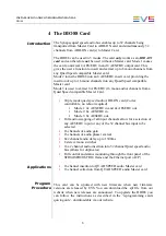
Page 10: ...o ADD ON card Cortex controllable no reboot required Mode 1 4x AES EBU in and 4x AESEBU out Mode 2 8x AES EBU in Mode 3 8x AESEBU out Full audio swapping of all input channels allow for a selection of any AES EBU input or any of the 32 channel bus input to be selected 16 channels of audio gain 16 channels of audio phase reversal 8x 2channel audio delay up to 1300ms 8 stereo mono switches 16x 2 cha...

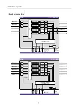
Page 11: ...HANNEL DELAY MONO SWITCH MONO SWITCH MONO SWITCH MONO SWITCH DIO88 MODE 2 8 IN RACK CONTROLLER ΜP AES EBU IN 1 2 SRC INTERNAL SYNAPSE BUS AES EBU IN 3 4 AES EBU IN 5 6 AES EBU IN 7 8 32 CHANNEL SRC SRC SRC 32CH IN QUAD SPEED MULTIPLEXING AUDIO BUS 32CH OUT 32CH IN 32CH OUT FROM MASTER TO MASTER TO NEXT ADD ON FROM NEXT ADD ON AES EBU IN 9 10 AES EBU IN 11 12 AES EBU IN 13 14 SRC AES EBU IN 15 16 S...

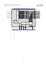
Page 12: ...1 12 AES EBU OUT 13 14 AES EBU OUT 15 16 AES EBU IN 1 2 AES EBU IN 3 4 AES EBU IN 5 6 AES EBU IN 7 8 AES EBU IN 9 10 AES EBU IN 11 12 AES EBU IN 13 14 AES EBU IN 15 16 GAIN PHASE GAIN PHASE GAIN PHASE GAIN PHASE GAIN PHASE GAIN PHASE GAIN PHASE GAIN PHASE GAIN PHASE GAIN PHASE GAIN PHASE GAIN PHASE GAIN PHASE GAIN PHASE GAIN PHASE GAIN PHASE 2 CHANNEL DELAY 2 CHANNEL DELAY 2 CHANNEL DELAY 2 CHANNE...

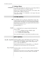
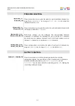
Page 13: ...ult setting is On In_Out In_Out determines how the synapse bus inputs and outputs work There s 3 modes 4In 4Out 4 AES EBU input and 4 AES EBU outputs 8In 8 AES EBU input and no outputs 8Out no inputs and 8 AES EBU outputs Refer to the block schematics for more details on the difference modes INPUT CONTROL Sel_Ch1 Sel_Ch16 With these settings you select which audio source you want to use for proces...

Page 14: ...channels 1 2 channels 3 4 channels 5 6 etc as being mono channels In which case for instance channel 1 and 2 will both contain a mix of channel 1 channel 2 or combined stereo channels Delay_CH_1 2 Delay_CH_15 16 These settings allow you to delay the audio of each pair of channels in a range of 0 to 1300 ms In steps of 0 01 ms Default is 0ms OUTPUT CONTROL Slot1 2 Slot31 32 These menu items are to ...

Page 15: ...n_1 AES In_8 If a valid signal is present on the corresponding input AES IN_1 till AES In_8 indicate OK NA indicates that no AES signal is present Ch_1_Inp Ch_16_Inp These status items indicate the status of the individual selected input channels This can be both from the master card via ADD ON or from the local inputs depending on what source you selected with settings Sel_Ch1 till Sel_Ch16 If th...

Page 16: ... are the priority setting In case of a Dolby data ERROR an Event will be generated at the priority or the audio carrier is falling away or audio data is in the range of 0 dBFS and 1 dBFS or the Encoder status is in error Reference Reference can be selected between 0 255 0 no event 1 255 are the priority setting If the reference is lost an Event will be generated at the priority What information is...

Page 17: ...ning Tags The tags defined for the DIO88 are Event Menu Item Tag Description Announcements 0 or NA 0 or NA Announcing of report and control values Audio Data 01hex AUDIO_ERROR 81hex AUDIO_OK Reference Status 02hex REF_LOSS 82hex REF_RETURN reference lost or returned The Priority The priority is a user defined value The higher the priority of the alarm the higher this value Setting the priority to ...

Page 18: ...CE This LED indicates the presence of a valid reference signal and that the DIO88 is locked to the master card DATA ERROR This led indicates different types of errors if there is an error in the Dolby encoding or the audio carrier is falling away or audio data is in the range of 0 dBFS and 1 dBFS CONNECTION This LED illuminates after the card has initialized The LED lights for 0 5 seconds every ti...

Page 19: ... CHANNEL DELAY MONO SWITCH MONO SWITCH MONO SWITCH MONO SWITCH DIO88 MODE 2 8 IN RACK CONTROLLER µP AES EBU IN 1 2 SRC INTERNAL SYNAPSE BUS AES EBU IN 3 4 AES EBU IN 5 6 AES EBU IN 7 8 32 CHANNEL SRC SRC SRC 32CH IN QUAD SPEED MULTIPLEXING AUDIO BUS 32CH OUT 32CH IN 32CH OUT FROM MASTER TO MASTER TO NEXT ADD ON FROM NEXT ADD ON AES EBU IN 9 10 AES EBU IN 11 12 AES EBU IN 13 14 SRC AES EBU IN 15 16...

Page 20: ...1 12 AES EBU OUT 13 14 AES EBU OUT 15 16 AES EBU IN 1 2 AES EBU IN 3 4 AES EBU IN 5 6 AES EBU IN 7 8 AES EBU IN 9 10 AES EBU IN 11 12 AES EBU IN 13 14 AES EBU IN 15 16 GAIN PHASE GAIN PHASE GAIN PHASE GAIN PHASE GAIN PHASE GAIN PHASE GAIN PHASE GAIN PHASE GAIN PHASE GAIN PHASE GAIN PHASE GAIN PHASE GAIN PHASE GAIN PHASE GAIN PHASE GAIN PHASE 2 CHANNEL DELAY 2 CHANNEL DELAY 2 CHANNEL DELAY 2 CHANNE...

Page 21: ...tor Panel The DIO88 can be used with the BPL11 back plane only BPL11 AES EBU IN OUT 1 2 AES EBU IN OUT 3 4 AES EBU IN OUT 5 6 AES EBU IN OUT 7 8 NOT CONNECTED AES EBU IN OUT 9 10 AES EBU IN OUT 11 12 AES EBU IN OUT 13 14 AES EBU IN OUT 15 16 ...

Page 22: ...hannels input on the master card If the master card can handle less then 32 channels the lowest channel numbers will be used as the ADD ON card will always generate 32 channels where some can be zero Channel shuffling is done in the ADD ON card The Master Card has only one setting to enable the quad speed audio bus Every Quad Speed ADD ON card takes 32 channels from the right hand ADD ON card and ...

Page 23: ...AUDIO IN QUAD SPEED MULTIPLEXING AUDIO BUS 32CH OUT 32CH IN TO ADD ON FROM ADD ON QUAD SPEED MULTIPLEXING AUDIO BUS AUDIO OUT AUDIO IN AUDIO OUT AUDIO IN AUDIO OUT AUDIO IN AUDIO OUT AUDIO IN AUDIO OUT AUDIO IN AUDIO OUT AUDIO IN AUDIO OUT AUDIO IN AUDIO OUT AUDIO IN AUDIO OUT AUDIO IN AUDIO OUT AUDIO IN AUDIO OUT AUDIO IN AUDIO FROM SYNAPSE BUS CONTAINING ALL 32 CHANNELS AUDIO FROM SYNAPSE BUS CO...

Page 24: ...verwriting slots that come from the right hand Master Card Channel slot 25 to 32 are left empty in this example Note The top example shows a logical way of how the ADD ON multiplexing could be performed However the insertion menu of for instance the DIO88 is much more flexible and allows putting every channel into any of the 32 channel slots The example below shows how the flexibility could be use...

Page 25: ......

Page 26: ......

Reviews: