Note that a V3X board with genlock must be installed as V3X #1 in first position (slot 2) in
the server. A V3X board with genlock can never be installed in any other slot, and thus
cannot be used instead of V3X #2 or #3. Doing so will result in conflicting electrical signals
inside the system.
Block Diagram
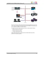
The block diagram of the V3X board with genlock is illustrated hereunder with the
connectors, jumpers and LEDs location:
HARDWARE TECHNICAL REFERENCE MANUAL XS Server 12.05
6. Boards Description
79
Summary of Contents for XS
Page 1: ...HARDWARE TECHNICAL REFERENCE MANUAL Version 12 05 July 2014 ...
Page 2: ......
Page 4: ......
Page 8: ......
Page 10: ......
Page 93: ...Connector Layouts HARDWARE TECHNICAL REFERENCE MANUAL XS Server 12 05 6 Boards Description 83 ...
Page 94: ...84 6 Boards Description EVS Broadcast Equipment SA Issue 12 05 B July 2014 ...
Page 96: ...Connectors Layouts 86 6 Boards Description EVS Broadcast Equipment SA Issue 12 05 B July 2014 ...
Page 98: ...Connectors Layouts 88 6 Boards Description EVS Broadcast Equipment SA Issue 12 05 B July 2014 ...
Page 100: ...Connectors Layouts 90 6 Boards Description EVS Broadcast Equipment SA Issue 12 05 B July 2014 ...
Page 113: ...Illustration HARDWARE TECHNICAL REFERENCE MANUAL XS Server 12 05 6 Boards Description 103 ...
Page 116: ......
Page 117: ......


