background image

77

4.0 M e chanic al in stallatio n

4.1  Tools required

•  Hex key size 5 and 6
•  Screw driver 2 mm

4.2  Robot installation on 
the telescopic pillar

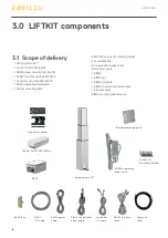
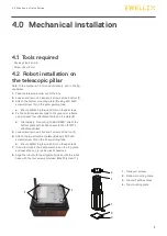
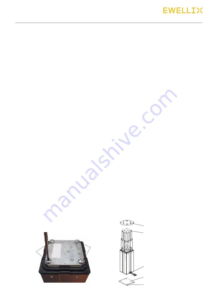
Refer to the numbers in 3.1 Scope of delivery, and in the fig-

ure below.
1.  Take the telescopic pillar out of the box
2.  Loosen and remove 4 transport screws at the bottom (1)
3.  Attach the bottom mounting plate (2) using 4 M10x40 

screws (screw 10) on the outer guiding tube
a.  Ensure tightening torque 40 Nm on these screws

4.  Fix the bottom plate securely to the ground or a frame 

using at least four attachment holes on the plate (3)
a.  Alternatively, if mounting to a SLIDEKIT, attach the 

bottom plate with 8x M6 screws to the LIFTKIT's 

attachment plate.

5.  Loosen and remove 4 transport screws at the top (1)
6.  Attach the top attachment plate (4) using 4 M10x40 

screws (screw 10) on the inner guiding tube.
a.  Ensure tightening torque 40 Nm on these screws

7.  If required, insert the 2 alignment pins on the top plate 

and press them in (or use a plastic hammer)

8.  Align the robot with the alignment pins and fix the robot 

base with the four screws provided (M6x20 (screw 11)) 

4.0  Mechanical installation

1

1

1.  Transport screws
2.  Bottom mounting plate
3.  Ground fixations holes
4.  Top mounting plate

1

4

3

1

2

Summary of Contents for LIFTKIT-0S-601

Page 1: ...CATEGORY MAX 2 LINES INSTALLATION OPERATION AND MAINTENANCE MANUAL LIFTKIT 0S ...

Page 2: ...t audience 4 2 0 Safety 5 2 1 Intended use 5 2 2 Safety elements 5 2 3 Application notes 5 2 4 Potential risks 5 2 5 E Stop setup and behavior 5 3 0 LIFTKIT components 6 3 1 Scope of delivery 6 4 0 Mechanical installation 7 4 1 Tools required 7 4 2 Robot installation on the telescopic pillar 7 5 0 Hardware connection SBOX 8 5 1 Hardware connection SBOX 8 5 2 Safety connection 8 5 3 Schematic SBOX ...

Page 3: ...l personnel working with the de vice must read and understand this manual before starting any work Strict compliance with all specified safety notes and instructions is a basic requirement for safety at work Moreover the accident prevention guidelines and general safety regulations applicable at the place of use of the de vice must also be complied with For a better representation of the circumsta...

Page 4: ...t www ewellix com TC 08023 EN THG TLG TLT operating manual TC 08005 EN SCU operating manual 1 5 Target audience This manual is intended for qualified technical personnel who install and use LIFTKIT in their application This manual and the corresponding operating manuals should be kept available for reference at all times Qualified personnel is able to carry out assigned work and to recognize and p...

Page 5: ... chain of the complete system prior to operating LIFTKIT The emergency stop function has to be connected in such a way that a disruption of the power supply or the activa tion of the power supply after a power disruption cannot cause a hazardous situation for persons and objects The emergency stop systems must always be freely ac cessible 2 4 Potential risks The following risks during LIFTKIT oper...

Page 6: ...t 1 Mount interface plates to pillar top and bottom 2 Connect all cables 3 Initialize LIFTKIT First use only LIFTKIT UR Others 3 1 Press both handswitch buttons at the same time until controller beeps 5sec 3 2 Move pillar downwards until end stop beep 3 3 Move pillar upwards until end stop beep 4 Screw robot to pillar install URCaps software ewellix com Ewellix All contents of this publication are...

Page 7: ...e using at least four attachment holes on the plate 3 a Alternatively if mounting to a SLIDEKIT attach the bottom plate with 8x M6 screws to the LIFTKIT s attachment plate 5 Loosen and remove 4 transport screws at the top 1 6 Attach the top attachment plate 4 using 4 M10x40 screws screw 10 on the inner guiding tube a Ensure tightening torque 40 Nm on these screws 7 If required insert the 2 alignme...

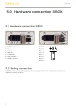
Page 8: ...tor 7 Ethernet Connector 8 K1 A1 9 K2 A1 10 K1 A2 11 K2 A2 12 K1 31 13 K1 32 14 K2 31 15 K2 32 A1 14 24 32 A2 13 23 23 24 13 14 A1 A2 31 32 31 1 2 3 4 5 6 7 8 9 10 11 12 13 14 15 5 2 Safety connection The SBOX L 01 has two integrated safety relay with forcibly guided contacts Their coil and feedback contacts are wired directly to the I O connector ...

Page 9: ...9 5 0 Hardware connection SBOX 5 3 Schematic SBOX 5 4 LIFTKIT connection setup ...

Page 10: ...multaneously for about 5 seconds until the SCU rattles and beeps Now the pil lar will run at 50 speed and force 4 Move the pillar downwards until it hits the end position The SCU controller beeps 5 Move the pillar upwards to the top position until it hits the end position The SCU controller beeps 6 Now the end positions have been identified and virtual limits have been set to always stop the pilla...

Page 11: ...aracter Parameters Parameters are defined for each command They must be in the right order Decimals All float values are sent with one decimal place More deci mals will be cut out Acknowledge Acknowledge Parameter 1 Parameter 2 Parameter 3 Description Command ok OK Everything is fine Command not found NF Command is not valid Command not allowed NA see status see status see status Command is valid ...

Page 12: ...d Ready Error get_type Initialized Connected Ready Moving Error get_typesAvailable Initialized Connected Ready Moving Error Require restart Virtual limits must be set again after changing the type Get status For getting the actual status from the SBOX L 01 send get_status n As a return you get the actual status in parameter one and a cause in parameter two if the state is not READY or MOVING There...

Page 13: ...aximum of one decimal place E g set_ virtualLimits 50 5 450 0 or set_ virtualLimits 40 500 If everything is correct it returns set_virtualLimits OK Move to absolute position For moving to an absolute position of the Liftkit send moveTo_absolutePosition position n The position is in mm as a float number with one decimal place E g moveTo_absolutePosition 120 5 or moveTo_absolutePosition 140 If every...

Page 14: ...te 4 Remove the SD card using a small tool like a pliers 5 Download and install one of these tools Raspberry imager from https www raspberrypi org downloads balenaEtcher from https www balena io etcher 6 Copy Image on SD card 6 1 Place SD card into your laptop 6 2 Do not format SD card 6 3 Start Raspberry imager or balenaEtcher 6 4 Choose Image 6 5 Select SD Card 6 6 Start writing process 7 Put SD...

Page 15: ...s Make sure that the 24 stays behind the static IP address 4 Put the file on an USB Stick 5 Remove all cables from the SBOX L 01 6 Open the Box 7 Insert USB Stick into the controller 8 Close the Box 9 Plug in the power cable into the SBOX L 01 10 Switch on the SBOX L 01 11 Wait 5 Minutes 12 Switch off the SBOX L 01 13 Remove all cables from the SBOX L 01 14 Open the Box 15 Remove USB Stick 16 Clos...

Page 16: ...rent max 10 A not protected Emergency stop STO up to PLe Cat 4 Communication Control interface TCP IP Positioning repeatability mm 1 Accessible positions any Feedback Position Status Soft start and stop Implemented for smooth operation Environment Type of protection IP40 in operational state Ambient temperature C 10 to 40 Max humidity 85 Altitude m 2 000 Vibration Stationary industrial environment...

Page 17: ... 6 40 40 340 141 5 2 13 5 50 5 75 75 360 365 87 Controller TLT Pillar Bottom fixation plate 180 70 140 200 180 146 UR3 4 M6 UR5 4 M8 UR10 UR16 4 M8 4 11 mm 8 6 3 mm 15 196 196 15 Stroke 4 30 mm deep Retracted length 4 without mounting plates Length 2 300 mm 146 163 129 3 M5 12 mm deep Holes also on opposite side 4 M10 30 mm deep 4 M10 101 SBOX 260 4 Ø 8 5 Control Unit Mount Hole Digital IO Power s...

Page 18: ... taken in the production of this catalog Ewellix does not take any responsibility for damage or other loss resulting from omissions or typographical errors The photo may differ slightly in appearance from the actual product Due to continuous improvements being made in our products the product s appearance and specifications are subject to change without notice PUB NUM TC 08046 EN February 2021 ...

Reviews: