Code
Function
Setting
Range Default
setting
Unit
No.1 compressor
time delay
Temperature
calibration
Temp. return
difference
-15
~
15
1
~
10
1
~
10
0
2
4
℃
℃
min
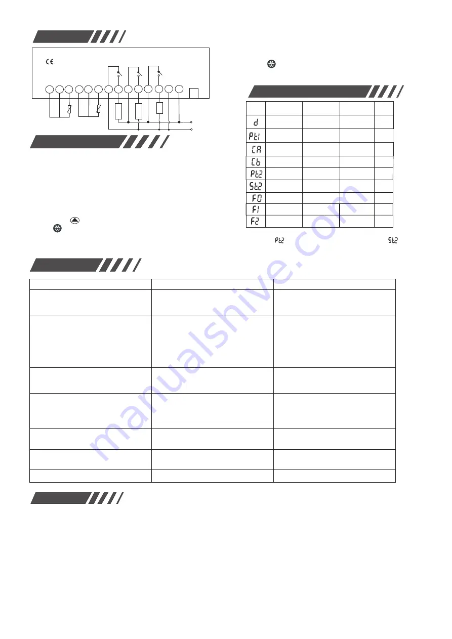
电 气接 线图
-15
~
15
0
℃
0
~
30
3
min
Defrost time
Defrost cycle
Dripping
time
after defrost
0
~
99
1
~
60
0
~
30
hr
min
6
10
2
-
135
~
50
-
5
.
0
℃
min
Feature
D
escriptions
:
Cooling
:
When
the
current
temperature
≥
set
temperature
+
temp.
return difference and
reach set “time dealy”
,
the relay is closed.
Stop Coolin
g:
When
the
current
temperature
≤
the
set tempe-
rature
,
the
cooling relay
is
off.
Enter defrost mode:
1. When the system finish running a set “running cycle”after defrost or
just after boot, it enters defrost mode (the load relay is off, defrost relay
is closed, defrost indicator is on), and set temp. displays the defrost temp.
(need to press after defrost termination to check).
2. Press key for 6s, enter defrost mode. (the relay is off, defrost relay
is close, defrost indicator is on)
Exit defrost mode:
1.Under the defrost mode, when the system runs over the set
defrost time, defrost relay and defrost indicator will be off,
system exits defrost mode and return to the normal control.
2. Press for 6s, defrost relay and defrost indicator will be
off, systems exits defrost mode and return to the normal co-
ntrol.
Defrost temp.
calibration
No.2 compressor
start temp.
No.2 compressor
time delay
Trouble shooting
Warnings
1. Please read this product instruction carefully and connect input/output plugs of
power & sensor to the corresponding sockets strictly by following connection
diagram strictly. Check again to make sure there is no mistake, tighten all the
screw of connection plugs again, and then connect the power afterwards. Otherwi-
se wrong connection will affect the usage and control, and even result in parts
burning.
2. Keep this product from away moisture, corrosive air and high magnetic field.
Otherwise the normal operation of this product will be affected.
3. All our products have passed strict quality inspections before leaving factory.
We provide one-year quality guarantee (which is limited to product itself ,and is
not responsible for any other joint and several liability) period for this product.
If you have any doubt or problem regarding to our
products, please contact our distributors and we will
provide you high-quality after-sale services.
Thanks you.
Guangzhou Ewelly Automatic Control Co., Ltd.
http://www.eliweli.com
Wiring diagram
Parameters for Procedure
No.2 compressor starts: when No.1 compressor operates over
the value “ ” or the air-returning temp.
≤
the value of “ ”
No.2 compressor stops: NO
.
1
&
2 compressors stop running sim-
ultaneously.
When defrost cycle is set to “0”, it will not enter defrost cycle, but
still can manually force to defrost.
No display when power is on.
Display but machine does not work
The sensor wiring is interfered or poorly
contacted or is tied with other cables.
The circuit is damaged.
Separate sensor wiring with power cables or
change shielded lines or check if the contact
is tight or not.
Real temperature is much different
to thermostat display.
The locations for the sensors are not correct or
sensor wiring is too long and its resistance is too
big. The wiring contact is poor and the sensor is
damaged.
All sensors should be installed into the correct
location. Enlarge the cross section of the expanded
wires. Make sure the wiring is sealed properly, water-
proof or moisture-proof of performance is qualified.
Change sensor if necessary.
Machine does not stop as soon as
the temperature reaches set value
The sensor is not correctly installed and cannot
measure the correct temperature. The contactor
of compressor failed.
Check if the sensor has accurately measured
the temperature or not. Change compressor relay.
Return difference value is too small or
the setting for pressure protection is incorrect.
Reset and enlarge the temperature value of return
difference. Adjust setting for pressure protection.
“
E1
”
is displayed
The sensor circuit is opened or shorted.
Check connection between the sensor wiring
and coupling end.
Failures
Causes
Solutions
Check to see if the power is short circuit
or the thermostat is faulty.
Check power supply and change fuse.
Check if there is 220V power input or change
thermostat with our distributor.
The setting temperature is higher than the
current temperature.
The heat protector is open circuit because the
pressure is over loads.
The heat protector within compressor is open
circuit.
Reset the necessary controlling temperature.
Check the reasons for overload and overheating.
After the trouble is solved, resume the work.
Displayed temperature is unstable or
there exists misplay
Compressor works with
over-frequency
Model
:
EW-285L
4 5 6 7 8 9
1 2 3
Return air
pipe Temp.
Room
Temp.
2-OFF PT100
Sensors
220V/AC
220V/AC
5A
10
11
5A
5A
Defrost
No
.
1
Compressor
12 1
4
No
.
2
Compressor
3 1


