Design and function
MIG/MAG welding
22
099-005592-EW501
16.07.2018
Figure 5-12
Item Symbol
Description
0
1
Carrier pin
For fixing the wire spool
2
Knurled nut
For fixing the wire spool
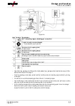
• Loosen knurled nut from spool holder.
• Fix welding wire reel onto the spool holder so that the carrier pin locks into the spool bore.
• Fasten wire spool using knurled nut.
5.2.3.3 Changing the wire feed rollers
Unsatisfactory welding results due to faulty wire feeding! Wire feed rollers must be suitable for
the diameter of the wire and the material.
• Check the roller label to verify that the rollers are suitable for the wire diameter.
Turn or change if necessary!
• use V-groove rollers with for steel wires and other hard wires,
• use U-groove rollers for aluminium wires and other soft, alloyed wires.
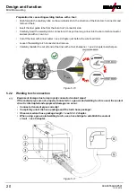
• Slide new drive rollers into place so that the diameter of the wire used is visible on the drive roller.
• Screw the drive rollers in place with knurled screws.
Figure 5-13
5.2.3.4 Inching the wire electrode
CAUTION
Risk of injury due to welding wire escaping from the welding torch!
The welding wire can escape from the welding torch at high speed and cause bodily
injury including injuries to the face and eyes!
• Never direct the welding torch towards your own body or towards other persons!


