Hardware Description
7 (20)
4
Hardware Description
4.1
Mechanical Layout and Interfaces
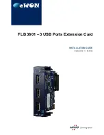
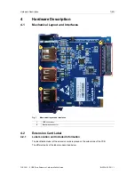
Fig. 1
Mechanical layout and interfaces
1
USB connectors
2
Back-plane connector
4.2
Extension Card Label
4.2.1
Label Location and Included Information
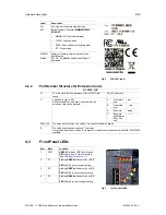
The identification label of the extension cards is placed on the solder side of the PCB.
The different parts of the label are described below:
FLB 3601 – 3 USB Ports Extension Card Installation Guide
IG-0024-00 EN 1.1

