


EX-TECH-SIG-SAS-12-SD125-150-TM-EN-REV04
the area over which both the sounder and beacon
requirement.
warning signal
must be audible and visible. The unit
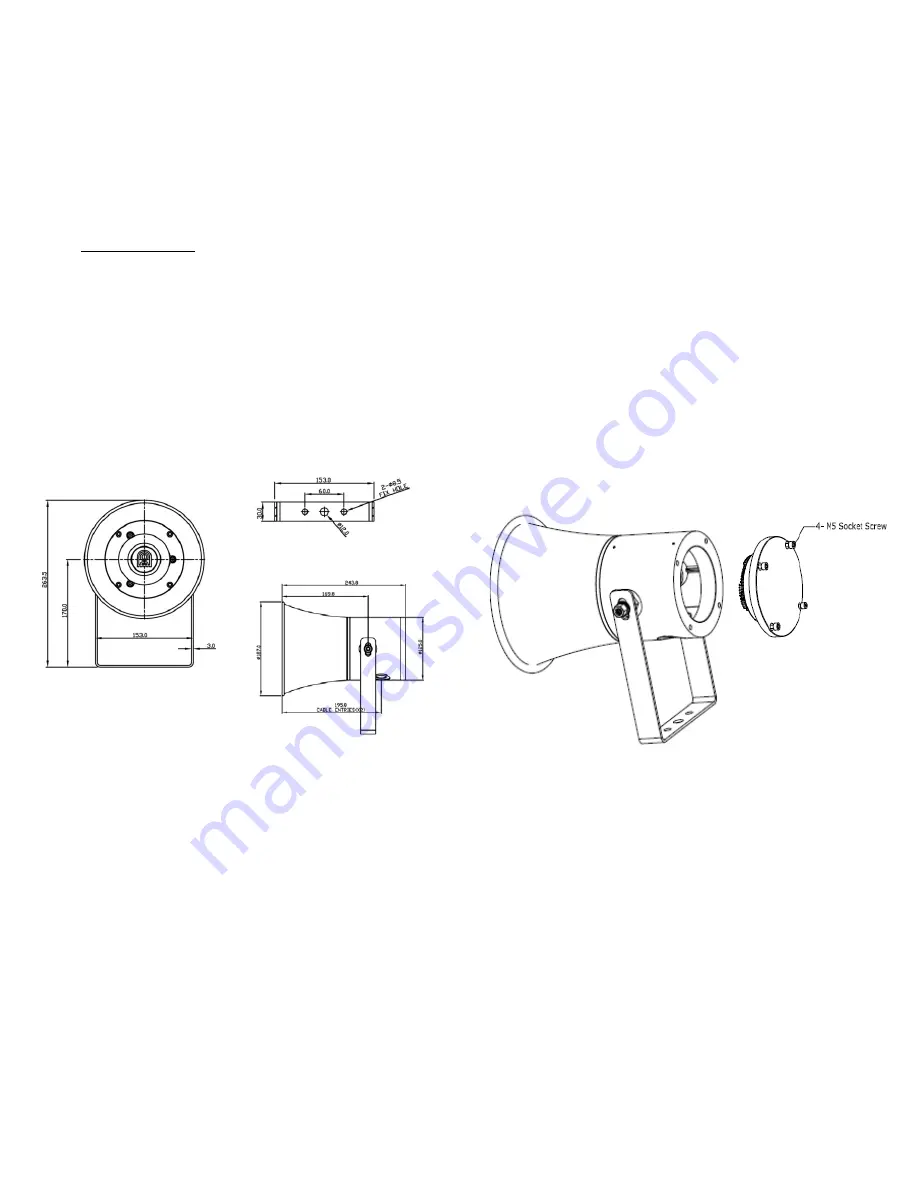
Remove End Cover
should only be fixed to servies that can carry the weight
of the unit.
Mounting
Bracket Mounting
Unscrew the six (6 for BC 150 and 4 for BC 125) M5
retained hex socket head screws of the end cover. This
will release the cover from the base. Before replacing the
cover, check that the flameproof joints are clean and not
damaged, the gasket is still retained in
The SD150/ 125 mounts ‘U’ shaped stainless steel
its groove
via a bracket by using one 12mm diameter and two
8.5mm diameter bolt holes in the center of the bracket.
The alignment and positions can be adjusted by
loosening the two M8 screws, which fastened the stainless
CAUTION
: Before removing the cover, ensure the power
to the product is isolated. Remove the six pieces of M5
socket screws to open the cover. Twist the cover gently
clockwise and anti-clockwise, whilst pulling away from the
steel bracket to the sounder. The sounder should be
base, until it comes off. Replace the cover in similar way,
positioned such that dust, debris or water cannot enter into
the horn opening.
but operate in reverse manner as above.
6.0 WIRING
General Requirement
EX-TECH SIGNALLING SAS recommends that all cables and
cores should be fully identified (suggest using cable from 2.0 to 2.5
mm²).
Ensure that all nuts, bolts and screws are secured. Ensure that only
the right and certified cable glands are used and earthed correctly.
Ensure that only the rig t and certified stopping plugs are used
to blank off unused gland entry points. In order to maintain the IP
rating of the product, we recommend SS316L for this application.
Cable Connection
The cable connection is connected with the terminal
blocks on the electronic
PCB
assembly located in the
flameproof enclosure of sounder. Cable connection should
be suitably approved for the installation requirements
Power Supply
up to 48V DC or 100-254V AC
PCB WIRING TERMINALS
Apply power supply to up to 48V DC o r 100-250V AC to ‘L’ &
‘N’ (See Fig 1)
Four Alarm Stages
No sound for Stage 1. There will be sounds for the subsequence
Stages:
Stage 1: apply power supply to ‘L’ & ‘N’
Stage 2; connect S1 to 0/ com
Stage 3: apply power supply to ‘L’ & ‘N’ and connect
S2 to 0/COM
Stage 4: apply power supply to ‘L’ & ‘N’ and connect S1, S2 to
0/COM. Stage DIY (Recording Sound) : supply to to ‘L’ apply
power& ‘N’ and connect DIY to 0/COM
Fig 1
Fig 2
3


