


EX-TECH-SIG-SAS-12-SD125-150-TM-EN-REV04
Pressing
Times
Default Setting
Option
1
1 minute
10 minute
2
5 minute
30 minute
3
10 minute
60 minute
4
Restore to the
sound
Restore to the
sound
7.0 TONE SELECTION
The sounder provides 63 tones to be selected for the
alarm stage 2 to 4. Three stages of alarm tones can be
preset via switch on the Sounder PCB.
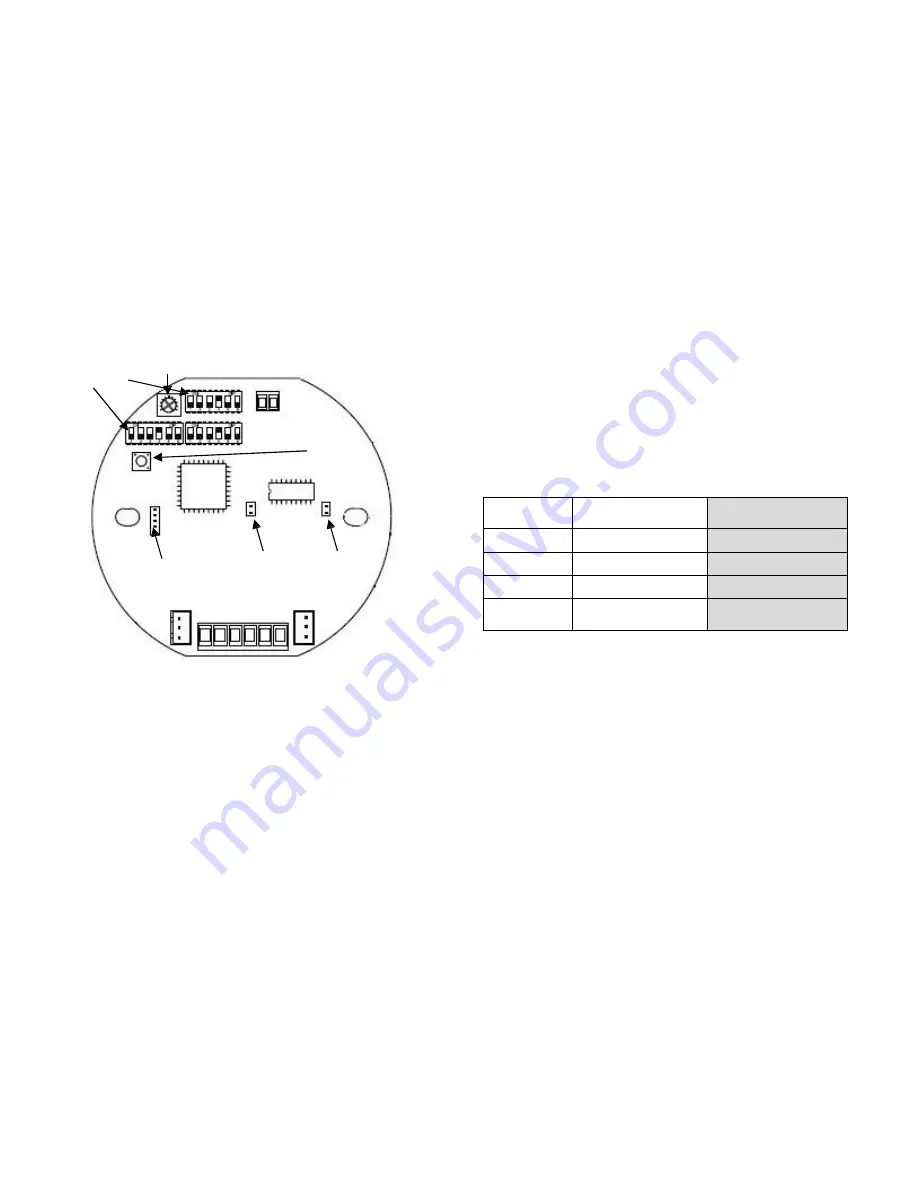
Tone Selection Switch
Use the three (3) DIP switches with 6 binary codes on the
Sounder PCB
to select tones (See Fig 3).
Tone Selection Table (see attached table 1)
DIP Switch
Potentiometer
Recording Procedure
1. Turn off S1 and S2;
2. Set up any DIP Switches as Tone 60-63 (refer to
Attached Table 1- Tone Selection Table);
3. Insert the Audio IN plug;
4. Press the Recording Button and hold the button
until the recording is finished.
CAUTION:
The sounder will begin to record after 3
seconds from pressing the button. Don’t release the button
when the recording is in process. The maximum of
recording time is 20 seconds.
10.0 SOUND PAUSE
The sound can pause by pressing the Recording Button.
(See Fig 3)
As the pausing period, please refer to the below table:
In order to have the option function, please inform EX-
TECH SIGNALLING SAS in advance before EX-TECH
SIGNALLING SAS begin the production of the sounder.
11.0 CABLE GLAND
8.0 VOLUME CONTROL
The sounder has a volume control to adjust the output
volume of the sounder component. To set the required
output volume, adjust the potentiometer-VR1 on the PCB
(See Fig 3). The potentiometer should be set to fully
clockwise position if maximum output volume is needed.
9.0 SOUNDER RECORDING
The sounder can provide 4 tones can be recorded by the
user. Use the Audio In and Recording Button (See Fig 3)
to record.
The SD150 series product has cable gland entries.
Only cable glands approved for Ex ‘d’ applications can
be used, which must be suitable for the type of cable
being used and also meet the requirements of the Ex
‘d’ flameproof installation standard EN/ IEC 60079-14.
SAFETY WARNING:
If the SD150 is used at high ambient
temperatures, i.e. over +40ºC, then the cable entry
temperature may exceed +70ºC and therefore suitable
heat resisting cable glands must be used, with a rated
service temperature of at least 95ºC.
If a high IP (Ingress Protection) rating is required, a
suitable sealing washer must be fitted under the cable
gland.
When only one cable entry is used, the other one must be
closed with an Ex ‘d’ flameproof blanking plug, which must
Recording Button
Reset
Pause Button
Audio In
L N S0 S1 S2 DIY
Fig 3
4


