background image

1/13/2005

6

EXAKTOR

®

 EXOA-2 BLADE COVER 

DUST COLLECTOR 

Installation

The

EXAKTOR

®

 BladeCover/Dust Collector has been designed to fit most table saws with its vertical Mast installed at

either the right or left hand side of the machine. In most cases the vertical mast will be installed at the right hand end of the
saw’s table or table extension, close to the rear edge of the table.

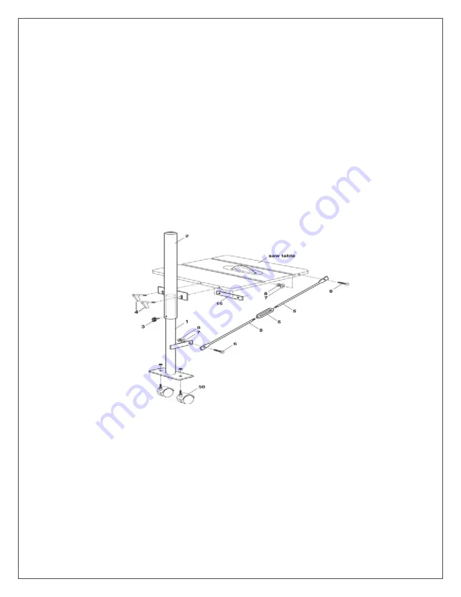
Mast Assembly

1.

With the Lower Mast (#1) resting on the floor, insert it into the bottom end of the Upper Mast (#2).

Adjust the overall length of the Lower and Upper Masts to where the top edge of the slotted Mounting Bracket, 
that is welded on the side of the Upper Mast, will be just below the top surface of the saw’s table or table 
extension. Lock the two Masts together with a Locking Knob (#3).

2.

Carefully place the slotted mounting bracket against the edge of the saw table, or table’s extension, close to 
the rear 

edge of the table. Make sure there is clearance behind the edge of the table to accommodate the Backing Plate 
(#15). Its two threaded holes must line-up with the slot in the mounting bracket

.

3.

Using the slots in the Mounting Bracket as a

template, drill a 1/4” hole at the top of each slot, 
through the edge of the table. Using two Locking
Levers (#4) and the Backing Plate (#15), fasten 
the Mounting Bracket to the edge of the table.

4.

The diagonal brace is used to hold the 

vertical mast in position. Use a ¼-20 x 1¼” Hex
Head Bolt (#6), Washer (#7) and ¼-20 Nut (#8) 
to attach one end of the Mast Brace (#5) to the 
bracket at the bottom end of the Lower Mast
(#1).

5.

Position the assembled Lower and Upper 
Mast so 

that it is vertical to the floor and square to the
surface of the saw table. Determine where to
place the 
unfastened end of the Mast Brace up under the 
rear edge of the saw’s table, or table extension so 
that when the brace is fixed in place, and the 
turnbuckle is tightened, the assembled Mast will 
be held vertical and square to the table surface 
and will not shift from that position. Drill an 
appropriate hole in the rear edge of the saw table 
or table extension and attach the

 upper end of the

Mast Brace to the edge of the underside of the table. 
Use Hex Head Bolt (#6), Washer (#7) and Nut (#8).

Summary of Contents for 34100

Page 1: ...x Quick Release Levers for removal and or attachment of the mast to the saw table x Counterbalance is located at the rear of the blade cover out of your line of sight x Two Rollers position the blade cover at the precise height above the work being processed x The blade cover has shatterproof lens allowing for complete visibility of the saw blade Prior to installing the EXAKTOR Blade Cover Dust Co...

Page 2: ...ecting the Guard Basket to the telescopic Boom makes dust extraction very efficient Installation is exceptionally easy The vertical mast stands on the floor and is adjustable to the height of the saw table The mast is fastened to the side of the saw table or table extension with two quick release levers For quick removal these levers release the upper part of the mast The mast supports a telescopi...

Page 3: ...gh the machine Tools work better and are safer when they work at their own speed 11 Do not overreach Keep proper footing and balance at all times 12 Do not reach behind the machine to grab a cutoff piece If the wood binds behind and against the blade or cutter it will kick back faster than you can let go 13 Disconnect the machine from electrical power before servicing and changing accessories such...

Page 4: ... table 20 Length of telescopic aluminum boom min 49 to max 80 Diameter of main boom tube 4 Diameter of inner boom tube 3 Guard Basket dimensions 18 x 4 x 4 high Clearance between guard basket and saw table 7 max Distance between the saw blade and vertical mast min 39 to max 70 Weight 47 lb ...

Page 5: ...1 13 2005 5 EXOA 2 VIEW OVERALL ...

Page 6: ...te the Backing Plate 15 Its two threaded holes must line up with the slot in the mounting bracket 3 Using the slots in the Mounting Bracket as a template drill a 1 4 hole at the top of each slot through the edge of the table Using two Locking Levers 4 and the Backing Plate 15 fasten the Mounting Bracket to the edge of the table 4 The diagonal brace is used to hold the vertical mast in position Use...

Page 7: ... Bolt 21 and Nut 22 are installed on the underside the outboard end of the Small Boom Tube 7 There are two Ǫ holes 6 apart in the Large Boom Tube for attaching the Boom Saddle 9 Push the Small Boom Tube out through the Large Boom Tube to gain access to these two Ǫ bolt holes from inside the Large Boom Tube 8 With the threaded hole in the tubular section of the Boom Saddle 9 facing in the direction...

Page 8: ...under the head of the Bolt and under the Ny Lock Nut 13 Position the small Roller Wheel 45 at the back end of the Guard Basket and attach with a 20 x 1 Shoulder Bolt 6 and 10 24 Ny Lock Nut 44 with a 1 4 washer 19 placed under the head of the Bolt and under the Ny Lock Nut 14 Use 20 Button 20x Ǫ Head Bolts 21 and 20 Nuts 22 to assemble the Guard Basket Frame 16 with the Top Lens 20 and the two Sid...

Page 9: ...e the forward end of the Long Arm 25 to the top of the Vertical Arm 27 using 5 16 18 TPI T Knob 28 17 Secure the forward end of the Short Arm 26 to the middle of the Vertical Arm 27 with a Ǫ 18 x 1 Shoulder Bolt 31 and 5 16 18 TPI Ny Lock Nut 40 18 Insert the plastic End Caps 34 into the forward end of the Long and Short Arms If the Caps tend to be a loose fit you can use a rubber band stretched a...

Page 10: ...le Hose is centered above the saw blade Secure the Guard Basket using the blade cover Lever 35 27 The rear of the Guard Basket has two vertical slots to allow the basket to come down over a splitter located behind the saw blade Use the four 6 32x Pan Head Screws 46 to attach a Cover Plate 36 or 37 to cover one or both slots as desired 28 Position the Counter Balance so that the weight of the Guard...

Page 11: ... OA27 Vertical Arm 1 OA28 T Knob 1 5 16 18 TPI BC29 Boom Clamp 1 OA30 T Knob 1 20 TPI Part Description Qty OA32 Counter Weight 1 OA33 Star Washer Ǫ 1 OA34 End Caps 2 OA35 Locking Lever 1 20 x ǫ OA39 Carriage Bolt 1 20 x 3 OA40 Ny Lock Nut 3 5 16 18 TPI Guard Basket Assembly Part Description Qty BC06 Shoulder Bolt 2 x 1 10 24 TPI ST19 Washer 6mm 4 BC16 Guard Basket Frame 1 BC18 Slide Bar 1 BC19 Sid...

Page 12: ...re or warranty service EXAKTOR Numbers The Exaktor Solutions Center is our one stop resource for all of your Exaktor tool needs You can download the latest Assembly Manuals read FAQ s and trouble shooting tips Visit us at http solutions exaktortools com For Customer Service 1 800 597 1343 Voice North America 1 905 568 4459 Voice Outside North America 1 905 568 4059 Fax Authorized Dealers For the n...

Page 13: ...remanufactured Product you receive will be covered by the balance of the warranty period remaining on the original Product You will keep the replacement Product that is sent to you and you must return or be billed up to the cost of the new product your original non working product which shall become the property of Exaktor You must call Exaktor Customer Service and if the representative cannot cor...

Reviews: