30
INSTALLATION
excel HE -
Installation and Servicing
J
H
M
L
K
U
T
P
R
S
N
ix7436
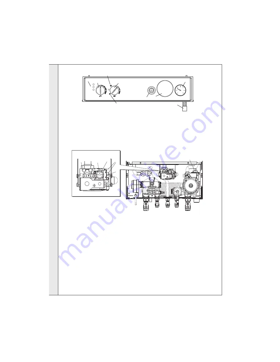
Gas Valve
39 INITIAL LIGHTING
1.
Check that the system has been filled and that the boiler is
not airlocked. Ensure the automatic air vent cap (H) is
open.
Note.
It is important the burner is not operated before the system is
fully vented of air. If it is necessary to operate the appliance
pump to assist venting of the air this must be done with the gas
service cock turned off.
2.
Refit the boiler RHS panel. Refer to Frame 45.
3.
Replace control panel and secure with fixing screws.
4.
Check that all the drain cocks are closed and that the CH
and DHW isolating valves (T, P and N) are OPEN.
5.
Check that the electrical supply is OFF.
6.
Check that the boiler on/off switch (A) is off.
7.
Check that the gas service cock (R) is OPEN.
8.
Slacken the screw in the inlet pressure test point (M) and
connect a gas pressure gauge via a flexible tube.
9.
Slacken the screw in the burner pressure test point (J) and
connect a gas pressure gauge via a flexible tube.
LEGEND
A.
Boiler On/Off switch.
B.
Main switch & CH thermostat knob.
C.
DHW thermostat knob
D.
Pressure gauge
E.
Operational lights (1 & 3) / Fault
indication light (2)
F.
Optional programmer
10.
Switch the electricity supply ON and check all external
controls are calling for heat.
11. CENTRAL HEATING
Set the main switch and CH thermostat knob (B) to
position shown in diagram and switch the boiler on/off
switch (A) to ON. The boiler control should now go through
its ignition sequence until the burner is established.
Green operational light 1 (E) will be illuminated when
burner is lit.
12.
If the boiler fails to light up to five times during the ignition
sequence, the boiler will go to lockout and red operational
light 2 (E) will be illuminated. To reset the ignition
sequence turn the main switch (B) to '0' wait until the boiler
reaches standby state, indicated by no fan or pump
running (this can take up to 10 minutes in an overheat
condition). Turn the main switch (B) to the winter setting,
wait for 2 seconds then set the main switch (B) back to the
desired position.
continued....................
G.
Condensate drain
H.
Automatic air vent
J.
Burner pressure test point
K.
CH max. pressure
adjustment nut
L.
DHW min. pressure
adjustment screw
if77434
3
2
1
C
E
B
Winter
Summer
A
F
D
G
Condensate
Drain
M.
Gas inlet pressure test point
N.
CH return isolating valve
P.
DHW inlet isolating valve
R.
Gas service cock
S.
DHW flow
T.
CH flow isolating valve
U.
Gas valve electrical connectors
I
N
ST
A
L
L
A
T
I
O
N


