37
SERVICING
excel HE -
Installation and Servicing
1.
Refer to Frame 51.
2.
Remove the boiler front, side and sealing panels. Refer to
Frames 44 and 45. Put the control box into the servicing
position. Refer to Frame 46.
3.
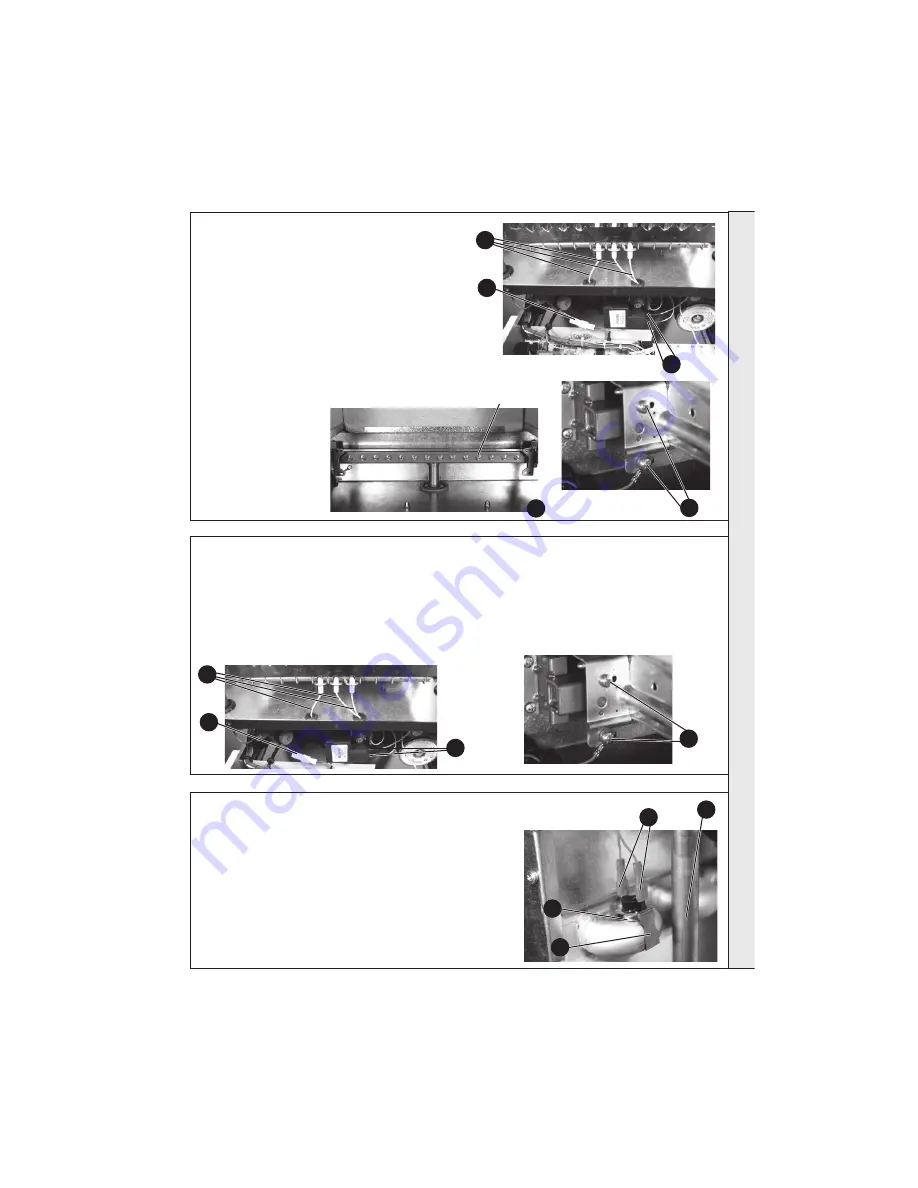
Carefully separate the in-line connector from the detection lead.
4.
Carefully pull off the two ignition leads from the side of the
ignition unit.
5.
Carefully pull the three leads through the rubber sealing
grommets.
6.
Remove the earth lead and the four burner fixing screws and
carefully withdraw the burner unit.
7.
Unscrew each injector from the manifold.
8.
Fit new injectors using new
copper washers provided.
9.
Re-assemble in reverse
order.
10.
Check the operation of the
boiler. Refer to Frame 50
and 51.
54 BURNER INJECTOR REPLACEMENT
1.
Refer to Frame 51.
2.
Remove the boiler front, side and sealing panels. Refer
to Frames 44 and 45. Put the control box into the
servicing position. Refer to Frame 46.
3.
Carefully separate the in-line connector from the detection
lead.
4.
Carefully pull off the two ignition leads from the side of
the ignition unit.
55 BURNER REPLACEMENT
1.
Refer to Frame 51.
2.
Remove the boiler front, side and sealing panels. Refer to Frames 44
and 45.
3.
Overheat Thermostat:
a.
Carefully pull off the 2 electrical connections.
b.
Unclip thermostat from pipe.
c.
Fit 2 electrical connections onto new thermostat
d.
Clip new thermostat onto pipe ensuring correct positioning on heat
exchanger manifold and re-assemble in reverse order.
4. UNDER NO CIRCUMSTANCES REFIT THE OVERHEAT THERMOSTAT
ONTO THE COLD RECUPERATOR RETURN PIPE.
5.
Check the operation of the boiler. Refer to Frame 50 and 51.
56 OVERHEAT THERMOSTAT REPLACEMENT
5.
Carefully pull the three leads through the rubber sealing
grommets.
6.
Remove the earth lead and the four burner fixing screws
and carefully withdraw the burner unit
7.
Fit the new burner unit.
8.
Re-assemble in reverse order.
9.
Check the operation of the boiler. Refer to Frame 50 and 51.
SER
VI
C
I
N
G
6
5
4
3
7
Injectors
4
5
3
6
3a
3b
3d
4


