48 / 66
5.3
LIMIT SWITCH SETTING AND REPLACEMENT
Base rotary limit switch is an electromechanical device for low voltage control circuits (EN 60947-1, EN
60947-5-1) to be used as electrical equipment on machines (EN 60204-1) in compliance with the
fundamental requirements of the Low Voltage Directive 2006/95/CE and of the Machine Directive
2006/42/CE.
The limit switch is designed for use in industrial environments under even severe climatic conditions
(operational temperature from
–40°C to +80°C, suitable for use in tropical environment). The equipment is
not suitable for use in environments with potentially explosive atmosphere, corrosive agents or a high
percentage of sodium chloride (saline fog). Oils, acids or solvents may damage the equipment; avoid using
them for cleaning. Do not connect more than one phase to each switch. Do not oil or grease the control
elements or the switches.
The installation of the limit switch shall be carried out by expert and trained personnel. Wiring shall be
properly done according to the current instructions. Prior to the installation and the maintenance of the limit
switch, the main power of the machinery shall be turned off.
Standard limit switches mounted in the LVC hoist allow 49 metre of travel. Optional limit switches for chain
lengths of 25-30m, 75m, and 100m are available.
320kg LVC model and 160kg D8+ hoist come without limit switch.
For a double reeved hoist like the 2000kg version, the length of chain travel is double. This reduces the lifting
height to 24.5 metres.
NB! Upper limit is based on a motor-up suspended chain hoist
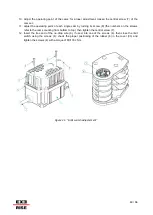
Steps Limit switch adjustment:
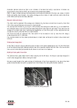
1. Loosen the Fixing screw (4) and remove the cover (3.)
2. Connect the limit switch shaft (2) to the reduction gear shaft avoiding any misalignment between the
two shafts.
3. Fix the limit switch Firmly in place to prevent abnormal vibrations of the equipment during operation;
use only the Fixing holes on the base (1) to ix the equipment.
4. Tighten the cable clamp (5) into appropriate place.
5. Insert the cable into the limit switch through the cable clamp (5).
6. Strip the cable to a length suitable for wiring the switches.
7. Tape the stripped part of the cable.
8. Clamp the wire into the cable clamp (5).
9. Connect the switches according to the contact scheme printed on the switches or to the wiring
scheme on the back of the instructions (use 6.3 mm Faston taps).


