CableSHARK
P3
User Guide
5
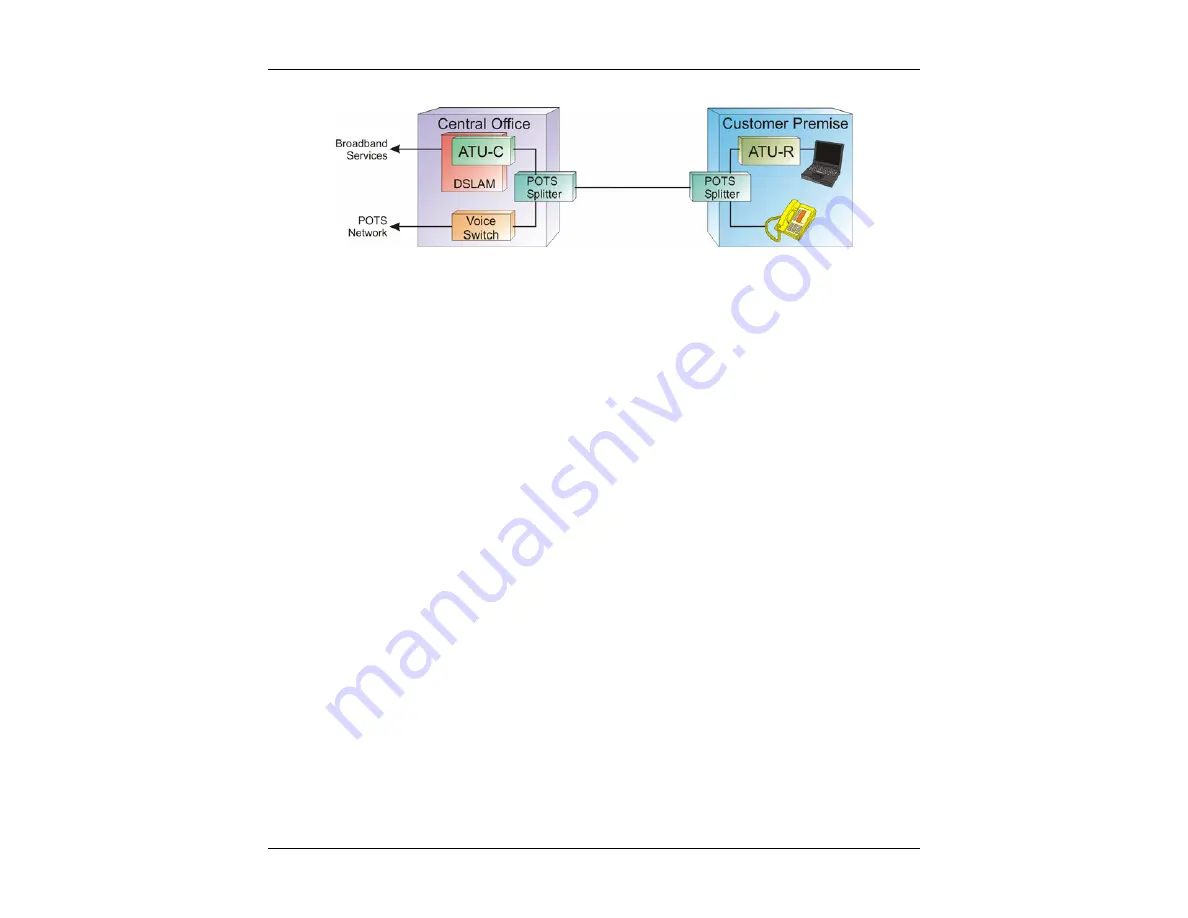
Figure 2C – ADSL Architecture
For service providers and customers alike, ADSL allows users to use their existing phone line to have both
high-speed Internet access as well as regular (including vital life-line) Plain Old Telephone Service (POTS).
ADSL signals are able to co-exist on the same loop with POTS service because they occupy a higher
frequency band than does POTS. ADSL typically will use the band of about 25 kHz to 1.104 MHz while
POTS uses 300 Hz to 3400 Hz. As a necessary precaution, a low pass filter is placed on the line to separate
ADSL signals from POTS signals. These so called POTS splitters or micro-filters must be in place for correct
operation. These small devices allow voice band frequencies to pass through to analog telephones while
keeping the high frequency signals of ADSL away from the phones. Likewise the input filters in ADSL
modems eliminate telephone signals from entering. In a similar fashion to ADSL and POTS on the same line,
ADSL can also co-exist with ISDN. However, since ISDN operates in the bandwidth up to 150 kHz, there are
fewer ADSL sub-channels that can be used resulting in a lower achievable data rate.
Two types of line coding exist for ADSL. An early scheme used a non-standards compliant CAP (Carrier-less
Amplitude / Phase Modulation) method. These days most ADSL DSLAMs and modems use the DMT
(Discrete Multi-Tone) technique. This book focuses on the DMT line coding as it is the DMT line code that is
recommended by ADSL standards bodies. These include ITU-T (G.992.1, G.992.2), ETSI, and ANSI /
Committee T1 (North America) (T1.413 Issue 2).
The DMT transmission scheme divides the frequency band from 0 Hz to 1.104 MHz into equally spaced sub-
channels or bins; this works out to 256 bins. Each bin occupies 4.3125 kHz of bandwidth. Since ADSL is
asymmetrical, the 1.104 MHz band is split once again into Upstream and Downstream bands. The Upstream
band carries information from the Customer Premise to the Network. The Downstream band carries
information from the Network to the Customer Premise.
Summary of Contents for CableSHARK P3
Page 1: ......
Page 10: ...VF DSL Cable Qualifier viii...
Page 12: ...VF DSL Cable Qualifier x...
Page 26: ...VF DSL Cable Qualifier 14...
Page 36: ...VF DSL Cable Qualifier 24...
Page 64: ...VF DSL Cable Qualifier 52...
Page 80: ...VF DSL Cable Qualifier 68...
Page 184: ...VF DSL Cable Qualifier 172...
Page 192: ...VF DSL Cable Qualifier 180...
Page 224: ...VF DSL Cable Qualifier 212...
Page 228: ...VF DSL Cable Qualifier 216...
Page 262: ...VF DSL Cable Qualifier 250 CSA Loop 6 CSA Loop 7 CSA Loop 8 Extended CSA Loop 9...
Page 263: ...CableSHARK P3 User Guide 251 Extended CSA Loop 10 Mid CSA Loop 0 Mid CSA Loop 1 Mid CSA Loop 2...
Page 264: ...VF DSL Cable Qualifier 252 Mid CSA Loop 3 Mid CSA Loop 4 Mid CSA Loop 5 Mid CSA Loop 6...
Page 265: ...CableSHARK P3 User Guide 253 ANSI Loop 2 ANSI Loop 3 ANSI Loop 4 ANSI Loop 5...
Page 266: ...VF DSL Cable Qualifier 254 ANSI Loop 6 ANSI Loop 7 ANSI Loop 8 ANSI Loop 9...
Page 267: ...CableSHARK P3 User Guide 255 ANSI Loop 11 ANSI Loop 12 ANSI Loop 13 ANSI Loop 15...
Page 268: ...VF DSL Cable Qualifier 256...
Page 286: ...VF DSL Cable Qualifier 274...
Page 292: ...VF DSL Cable Qualifier 280...
Page 294: ...VF DSL Cable Qualifier 282...
Page 316: ...VF DSL Cable Qualifier 304...
Page 318: ...VF DSL Cable Qualifier 306...
Page 319: ...CableSHARK P3 User Guide 307 Notes...
Page 320: ...VF DSL Cable Qualifier 308...


