VF / DSL Cable Qualifier
200
12.3 RFL Hints
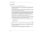
The following are useful hints for using the CableSHARK RFL function.
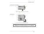
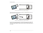
1. Use a strap that is made of 18 AWG (1.0 mm) cable. Strap together the faulty conductor to the
good pair. Do not use smaller gauge of wire for the strap as this will have a higher resistance and
will affect the measurement.
2. If AC voltage is being induced into the circuit under test, the RFL measurement will be incorrect.
The best solution for this matter is to move closer to the Central Office as the CO as a lower
impedance compared to testing in the middle of the cable.
3. 88mH Load coils typically add 4.5 ohms to the distance reading. That is about 150 ft (45 meters).
Using the CableSHARK’s Load Coil Detection test, determine how many load coils are on the line
and subtract 150 feet (45 meters) for every load coil that is part of the distance reading. 88 mH load
coils are placed 3000 ft from the CO and then every 6000 ft towards the customer. If the RFL
indicates a problem at 12,000 ft, subtract 300 ft from that distance (2 load coils x 150 feet).
4. It may be necessary to put 10kohm matched resistor on the input of the RFL measurement to
discharge voltage on the line before taking a measurement if voltage is detected.
5. Temperatures play an important part in determining the length of a cable (cable resistance changes
with temperature). Temperatures can vary over the length of a cable and can be extreme. Aerial
cables in direct sunlight will have a higher temperature than the air temperature.
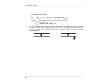
6. To convert temperatures from Fahrenheit to Celsius and vice versa, use the following calculations:
F = [ ( 9 / 5 ) x C ] + 32
C = ( 5 / 9 ) x ( F – 32 )
7. If a Bridge Tap has a fault, the RFL measurement will indicate the location of the start of the Bridge
Tap
only.
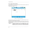
8. If the RFL measurement gives a negative distance, there can be AC voltage being induced on the
line or one of the cable section information entered into the CableSHARK’s RFL Setup screen
contains erroneous information.
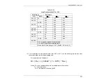
9. Different gauges of cable have different loop resistances. The following table is for typical wire
gauges and can be different from region to region and manufacturer to manufacturer.
Summary of Contents for CableSHARK P3
Page 1: ......
Page 10: ...VF DSL Cable Qualifier viii...
Page 12: ...VF DSL Cable Qualifier x...
Page 26: ...VF DSL Cable Qualifier 14...
Page 36: ...VF DSL Cable Qualifier 24...
Page 64: ...VF DSL Cable Qualifier 52...
Page 80: ...VF DSL Cable Qualifier 68...
Page 184: ...VF DSL Cable Qualifier 172...
Page 192: ...VF DSL Cable Qualifier 180...
Page 224: ...VF DSL Cable Qualifier 212...
Page 228: ...VF DSL Cable Qualifier 216...
Page 262: ...VF DSL Cable Qualifier 250 CSA Loop 6 CSA Loop 7 CSA Loop 8 Extended CSA Loop 9...
Page 263: ...CableSHARK P3 User Guide 251 Extended CSA Loop 10 Mid CSA Loop 0 Mid CSA Loop 1 Mid CSA Loop 2...
Page 264: ...VF DSL Cable Qualifier 252 Mid CSA Loop 3 Mid CSA Loop 4 Mid CSA Loop 5 Mid CSA Loop 6...
Page 265: ...CableSHARK P3 User Guide 253 ANSI Loop 2 ANSI Loop 3 ANSI Loop 4 ANSI Loop 5...
Page 266: ...VF DSL Cable Qualifier 254 ANSI Loop 6 ANSI Loop 7 ANSI Loop 8 ANSI Loop 9...
Page 267: ...CableSHARK P3 User Guide 255 ANSI Loop 11 ANSI Loop 12 ANSI Loop 13 ANSI Loop 15...
Page 268: ...VF DSL Cable Qualifier 256...
Page 286: ...VF DSL Cable Qualifier 274...
Page 292: ...VF DSL Cable Qualifier 280...
Page 294: ...VF DSL Cable Qualifier 282...
Page 316: ...VF DSL Cable Qualifier 304...
Page 318: ...VF DSL Cable Qualifier 306...
Page 319: ...CableSHARK P3 User Guide 307 Notes...
Page 320: ...VF DSL Cable Qualifier 308...

