Introducing the CT440
CT440
9
Product Overview
Product Overview
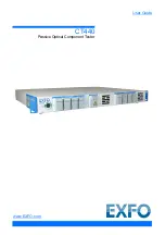
The CT440 is made of two complementary parts:
The CT440 instrument, which makes measurements during the wavelength scan
The CT440 software (GUI), which takes the data from the instrument and performs all
the analysis
The CT440 is delivered with the following accessories:
Rack mounting brackets
A power supply cord
A USB-A to USB-B cable
A USB key containing:
The CT440 installation package (GUI software, USB driver and CT440 library for
remote control)
User documentation
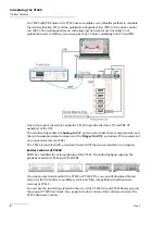
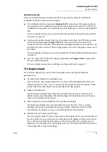
Front Panel
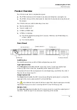
On/Off Button
The On/Off button turns on/off the CT440 and lights the green LED.
Input Optical Port(s)
The
TLS
Input
label identifies the APC connectors used to connect the tunable laser
source(s) (up to four connectors, depending on the model) to the CT440.
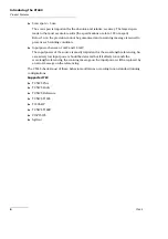
On models with more that one input port, the wavelength range must follow the order of
the ports (lower range in port 1).
Output Optical Port
The
Output
label identifies the APC connector providing the signal output to connect the
input port of the device under test (DUT) with an SMF fiber.
The
label indicates the location of the laser output. This output requires special safety
instructions for proper use (see
Connecting the DUT to the CT440
Detector Ports
The
Detector Array
label identifies the PC connectors used to connect the output ports of
the device under test (up to four connectors depending on the model).
On/Off button
Input optical ports
Output optical port
Rack-mount bracket
Detector ports
Summary of Contents for CT440 Series
Page 1: ...User Guide CT440 Passive Optical Component Tester www EXFO com...
Page 6: ......
Page 30: ......
Page 96: ......
Page 162: ......

