Setting Up Your CT440 for Measurements
26
CT440
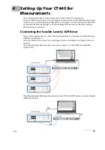
Connecting the Tunable Laser(s) (GPIB Use)
Before starting:
Make sure you have the following material:
One or more tunable laser(s).
A GPIB card or GPIB controller (if the CT440 is used in trigger mode, this adapter is not
needed: see
For TUNICS or T100S-HP lasers, the CT440 has been developed and tested using the
NI GPIB controller.
If you want to use another vendor’s GPIB/USB adapter, uninstall any existing
USB/GPIB driver from your computer before installing the new USB/GPIB driver.
Make sure the controller driver is installed on your computer according to the
manufacturer’s guidelines, and in the controller’s utility, make sure the GPIB
interface is installed as the primary board 0 (GPIB0).
The sufficient number of GPIB cables (one GPIB cable per TLS) to connect the
computer to the tunable laser(s).
The sufficient number of optical patch cords with the appropriate connector types,
corresponding to the one mounted on your CT440 (see
page 7 for available models) and the appropriate fiber type, corresponding to your
CT440.
To connect the tunable laser(s):
1.
Using the GPIB cable(s), connect your computer to the TLS.
2.
Using a clean APC patch cord, connect the TLS to the input port(s) of the CT440.
If you want to connect two or more TLS, follow the instructions below:
2a.
Connect the TLS with the lowest wavelength range to the TLS Input connector 1 of
the CT440.
The wavelength ranges of the TLS used must follow the CT440’s input port order:
the source with the lowest wavelength range must always be connected on port 1,
and the input port 1 must always be used.
2b.
Connect the TLS with the next lowest starting wavelength to port 2, and so on.
Wavelength ranges of multiple TLS don’t have to overlap for the system to work.
For instance, you can connect an O-band (1260nm-1360nm) TLS to CT440 input
port 1 and an CL-band (1500nm-1630nm) TLS to port 2.
3.
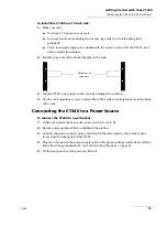
Plug the power cord(s) of the TLS.
4.
Turn on the TLS.
C
AUTION
Make sure you use the appropriate connector and fiber types.
Make sure optical connectors are perfectly clean. It is essential to achieve
optimum system performance, especially for PDL measurements (see
Summary of Contents for CT440 Series
Page 1: ...User Guide CT440 Passive Optical Component Tester www EXFO com...
Page 6: ......
Page 30: ......
Page 96: ......
Page 162: ......


