Performing Measurement Scans
38
CT440
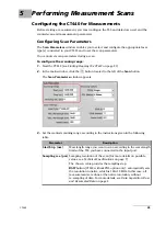
Configuring the CT440 for Measurements
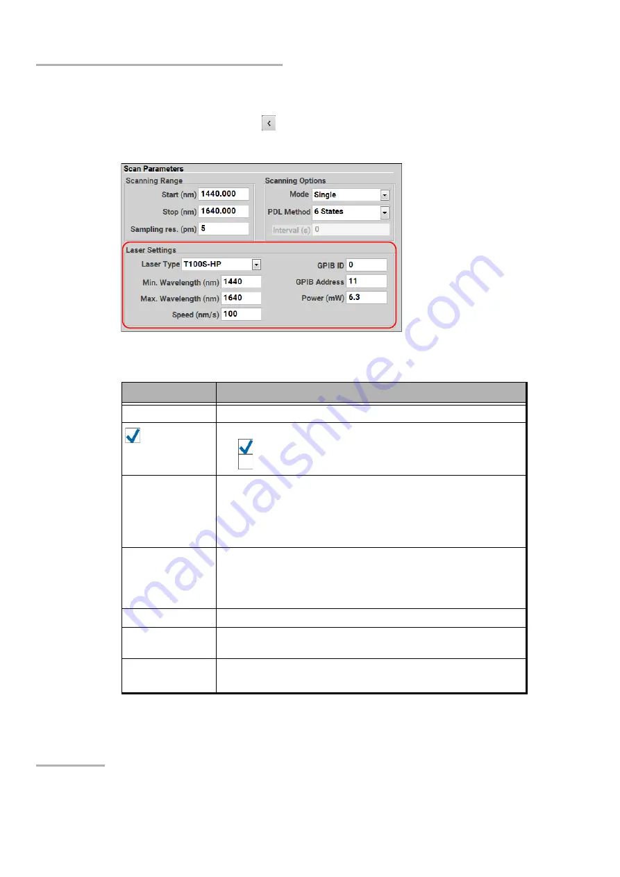
To configure the laser settings:
1.
Start the CT440 (see
2.
In the main window, click the
button located to the left of the
Scan
button.
The
Scan Parameters
window appears.
3.
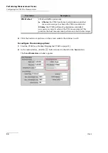
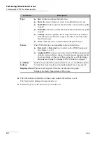
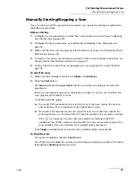
Set parameters for the laser(s) connected to the CT440 (1 tab per connected laser),
according to the instructions given in the following table.
4.
Click the button or anywhere on the screen outside the window to exit.
Parameter
Description
Laser Type
Type of the laser connected to the CT440.
Selected
Only applies to CT440 with two or more TLS input ports.
: the laser is activated and will be used for the scan.
: the laser is disabled and won’t be used for the scan.
Min./Max.
Wavelength (nm)
Minimum and maximum wavelength (in nm) that the TLS can
provide. You cannot select wavelength values outside the
operating wavelength range of the CT440 type connected to your
The TLS must cover at least 5 nm.
GPIB ID
GPIB interface ID of the selected tunable laser GPIB controller.
Refer to your GPIB controller firmware to set the correct ID
number.
Possible values: 0 to 100.
GPIB Address
GPIB address of the selected tunable laser.
Speed (nm/s)
Speed of the tunable laser is nm/s, according to the selected laser
speed specifications.
Power (mW)
Output power for the tunable laser.
Possible values: see
Summary of Contents for CT440 Series
Page 1: ...User Guide CT440 Passive Optical Component Tester www EXFO com...
Page 6: ......
Page 30: ......
Page 96: ......
Page 162: ......


