Performing Measurement Scans
40
CT440
Configuring the CT440 for Measurements
4.
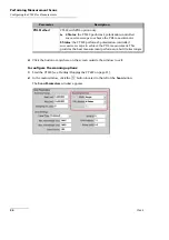
Click the button or anywhere on the screen outside the window to exit.
The Trace button displays the parameters set.
5.
Perform steps 2 to 4 for each trace you want to set.
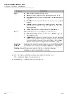
Type
Live
: the trace pictures the next scan.
Store
: the trace is frozen. It won't be modified by next scans.
Hold Min
: the trace pictures the minimum scanned values point
to point.
Hold Max
: the trace pictures the maximum scanned values point
to point.
Average
: the trace pictures the average of all scans performed
from the first scan. This trace type is useful to reduce the noise
level if necessary.
None
: clears the trace content and deactivates the trace.
Source
The CT440 detector corresponding to the selected trace.
Detector 1
to
Detector 4
are located on the CT440 front panel
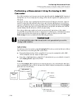
Analog In BNC
connector is located on the CT440 rear panel and
enables you to perform voltage or optical power measurements.
For more details on the use of this connector, see
Measurement Using the Analog In BNC Connector
Load/Save
buttons
Buttons to save/load the selected trace in .csv or .tra (CT440 specific
format). For more details, see
Displayed trace
This area only appears if the trace is displayed on graph.
Displays the main characteristics of the trace.
Parameter
Description
Summary of Contents for CT440 Series
Page 1: ...User Guide CT440 Passive Optical Component Tester www EXFO com...
Page 6: ......
Page 30: ......
Page 96: ......
Page 162: ......

