Performing Measurement Scans
42
CT440
Setting up a Triggered Scan
Setting up a Triggered Scan
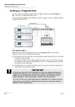
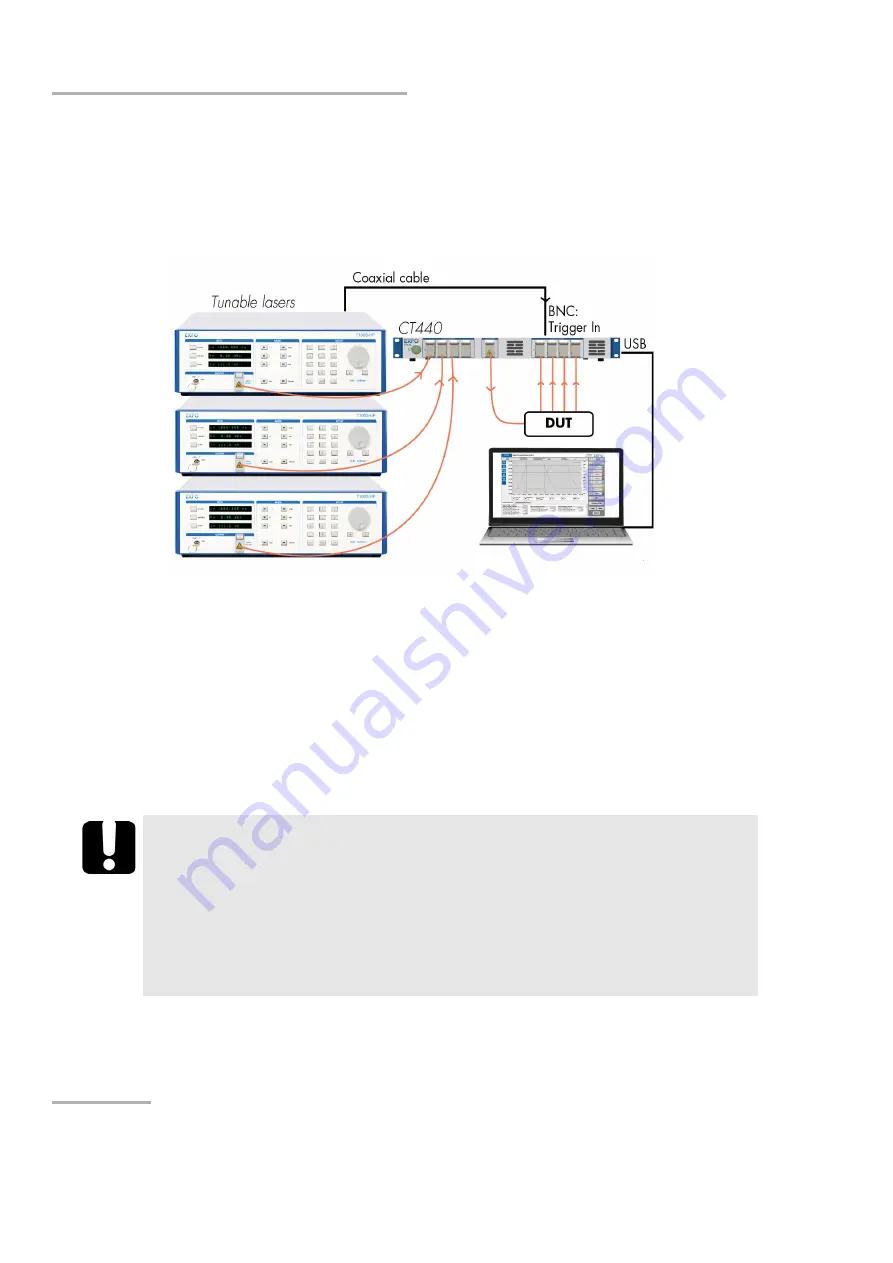
You can control the CT440 measurement with a trigger signal by using the
Trigger In
BNC connector, as explained in this section.
The following figure illustrates the hardware setup for a triggered scan: no GPIB controller is
required, but a BNC cable.
Scan Synchronization
When the TTL signal is emitted from the laser to the
Trigger In
BNC connector, the
start/stop of the scan are synchronized as follows:
When the TLS has reached the start wavelength, the trigger signal rises (0 to 1) and the
CT440 starts collecting data.
On CT440 with PDL option: if PDL measurement is selected in one of the trace menus,
the CT440 measures one state of polarization (out of 4 or 6 depending on the selected
parameter) at each rising edge.
At falling edge (1 to 0) of the input signal, the TLS is expected to have reached its end
value and the internal analysis ends.
I
MPORTANT
In Continuous Trig mode, the CT440 waits for the end of all data exchanges and
analysis before starting a new measurement. If data communication or software
analysis is not over when the next logic 1 signal arrives, the CT440 ignores the
signal and waits for the following logic 1 to start a new measurement.
On CT440 with PDL option:
if PDL measurement is selected in one of the trace menus,
several sweeps are needed to complete the measurement. Each sweep requires a
triggered start to be performed.
Summary of Contents for CT440 Series
Page 1: ...User Guide CT440 Passive Optical Component Tester www EXFO com...
Page 6: ......
Page 30: ......
Page 96: ......
Page 162: ......

