background image

Maintenance

62

FVA-3100

Cleaning Connectors Equipped with EUI/EUA Adapters

Cleaning Connectors Equipped with EUI/EUA 

Adapters

Regular cleaning of connectors equipped with EUI/EUA adapters will help 
maintain optimum performance. There is no need to disassemble the unit.

To clean connectors:
1.

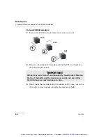
Remove the EUI/EUA adapter from the module to expose the optical 
connector baseplate and ferrule.

2.

Use a lint-free wiping cloth and deposit 

only one drop 

of isopropyl 

alcohol on it.

I

MPORTANT

If any damage occurs to internal connectors, the module casing will 
have to be opened and a new calibration will be required.

I

MPORTANT

Alcohol may leave traces if used abundantly. Avoid contact between 
the tip of the bottle and the wiping cloth, and do not use bottles 
that distribute too much alcohol at a time.

Push

Turn

Pull

1

2

3

Artisan Technology Group - Quality Instrumentation ... Guaranteed | (888) 88-SOURCE | www.artisantg.com

Summary of Contents for FVA-3100

Page 1: ...ss underutilized and idle equipment along with credit for buybacks and trade ins Custom engineering so your equipment works exactly as you specify Critical and expedited services Leasing Rentals Demos...

Page 2: ...EXFO AMERICA 4275 Kellway Circle Suite 122 Addison TX 75001 USA Tel 1 972 836 0100 Fax 1 972 836 0164 EXFO EUROPE Le Dynasteur 10 12 rue Andras Beck 92366 Meudon la For t Cedex FRANCE Tel 33 1 40 83 8...

Page 3: ...EXFO AMERICA 4275 Kellway Circle Suite 122 Addison TX 75001 USA Tel 1 972 836 0100 Fax 1 972 836 0164 EXFO EUROPE Le Dynasteur 10 12 rue Andras Beck 92366 Meudon la For t Cedex FRANCE Tel 33 1 40 83 8...

Page 4: ...he equipment described herein bears the symbol the said equipment complies with the applicable European Union Directive and Standards mentioned in the Declaration of Conformity Artisan Technology Grou...

Page 5: ...parties that may result from its use No license is granted by implication or otherwise under any patent rights of EXFO EXFO s Commerce And Government Entities CAGE code under the North Atlantic Treaty...

Page 6: ...riable Attenuator 15 Selecting the Display Intensity 15 Locking Control Key Access 17 Managing the Wavelength Shortlist 19 Selecting the Attenuation 23 Selecting and Using an Attenuation Display Mode...

Page 7: ...71 Finding Information on the EXFO Web Site 71 Contacting the Technical Support Group 72 Transportation 73 9 Warranty 75 General Information 75 Liability 76 Exclusions 76 Certification 76 Service and...

Page 8: ...Declaration of Conformity CSA Information This unit received CSA certification under the model name GO The CSA Certificate Number is 162451 The C US indicator adjacent to the CSA Mark signifies that t...

Page 9: ...nate from these cables IMPORTANT The AC adapter provided with this product is equipped with a shielded three wire power cord and plug Use this power cord in conjunction with a properly grounded electr...

Page 10: ...Equipment for Measurement Control and Laboratory Use Part 1 General Requirements EN 61000 3 2 1995 Electromagnetic Compatibili ty Part 3 Limits Section 2 Limits for Harmonic Current Emissions EN 61000...

Page 11: ...Artisan Technology Group Quality Instrumentation Guaranteed 888 88 SOURCE www artisantg com...

Page 12: ...nimize your loss budget The FVA 3100 Variable Attenuator has a program function which allows you to create custom programs such as automatic attenuation scan The variable attenuator has the versatilit...

Page 13: ...own Attenuation Program Setup Output port Offset mode access Reference mode access Confirmation button Enter Absolute mode access Wavelength control Arrow buttons for menu navigation and parameter set...

Page 14: ...llowing two conditions 1 this device may not cause harmful interference and 2 this device must accept any interference received including interference that may cause undesired operation Made in Canada...

Page 15: ...ut which ensures accurate power level monitoring Typical Applications The FVA 3100 Variable Attenuator is ideal for manufacturing and laboratory applications such as system characterization EDFA compo...

Page 16: ...loss or attenuation between the input and the output ports of the Variable Attenuator including the loss of its own internal connectors after performing a reference reading with a power meter IMPORTA...

Page 17: ...Artisan Technology Group Quality Instrumentation Guaranteed 888 88 SOURCE www artisantg com...
Page 18: ...harm or injury Do not proceed unless you understand and meet the required conditions CAUTION Refers to a potential product hazard It requires a procedure which if not correctly followed may result in...

Page 19: ...cable depends on the cable New plugs should meet the local safety requirements and include the following features adequate load carrying capacity ground connection cable clamp WARNING Do not install o...

Page 20: ...owered via an auto transformer for voltage reduction connect the common terminal to the grounded power source pole Insert the power cable plug into a power outlet with a protective ground contact Do n...

Page 21: ...Artisan Technology Group Quality Instrumentation Guaranteed 888 88 SOURCE www artisantg com...

Page 22: ...x the angle iron using four flat Phillips screws 2 Fix the rackmount bracket to the frame using two round Phillips screws 3 Fix the rackmount stiffener using two flat Phillips screws for the front pan...

Page 23: ...into the rackmount and tighten it from underneath using the four cover fixing screws If measurement X on the illustration exceeds 11 125 in fix the unit into the four holes identified as A Otherwise...

Page 24: ...read only memory current shutter state current display mode current attenuation setting current wavelength shortlisted wavelengths each wavelength offsets step size remote control settings programmed...

Page 25: ...to move until EXIT is displayed then press ENTER IMPORTANT Some internal mechanisms can sometimes take a few seconds to adjust depending on the operation performed While the Variable Attenuator is per...

Page 26: ...urn off the display without turning off the unit To select the display intensity 1 Press on the Setup VARIABLE ATTENUATOR FVA 3100 Offset ENTER Abs Up Shutter Ref Down Attenuation Program Setup Confir...

Page 27: ...y the dimmer status LO HI or OFF 5 Press ENTER Note Setting the dimmer to OFF turns off the display Press any button to turn the display back on VARIABLE ATTENUATOR FVA 3100 Offset ENTER Abs Up Shutte...

Page 28: ...ys the blue buttons on the front panel of the unit To lock the control key access 1 Press Setup 2 Use the left right arrows until LOCKOUT is displayed 3 Press ENTER VARIABLE ATTENUATOR FVA 3100 Offset...

Page 29: ...rts to the settings that were active before you entered the Setup menu All control keys are deactivated To unlock the keypad 1 Press on the Setup button 2 Press ENTER The UNLOCKED message is briefly d...

Page 30: ...switching to a new wavelength the attenuator motor will reposition itself to keep the current attenuation value for the new wavelength Refer to Technical Specifications on page 79 for more informatio...

Page 31: ...e first digit will flash 5 Use the up down arrows to change the flashing digit and the left right arrows to activate the next digit 6 Once all digits are set press ENTER 7 To exit the Setup menu press...

Page 32: ...lashing 5 Set all the wavelength digits to zero To do so use the up down arrows to change the flashing digit and the left right arrows to activate the next digit 6 Press ENTER 7 To exit the Setup menu...

Page 33: ...elengths from the shortlist 1 Press the Setup button 2 Press the left right arrows until LAMBDA is displayed 3 Press the up down arrows until DEL ALL appears in the lower portion of the display 4 Pres...

Page 34: ...nuation to a specific value The available step sizes are 0 01 0 02 0 05 0 1 1 2 5 10 20 and 50 dB Note Selecting a larger step size allows for faster attenuation scanning To change the step size 1 Pre...

Page 35: ...tenuator is 0 005 dB the third digit after the decimal point must always be 5 The new attenuation setting will be rejected if its third digit is not 5 For more information on the variable attenuator o...

Page 36: ...ation 1 Select a wavelength by clicking on the wavelength control until you reach the desired wavelength 2 Press the Abs button 3 Press the Attenuation button and set an attenuation of 000 00 dB 4 Pre...

Page 37: ...nd set an attenuation of 999 99 dB 4 Press ENTER The Variable Attenuator will default to the maximum attenuation VARIABLE ATTENUATOR FVA 3100 Offset ENTER Abs Up Shutter Ref Down Attenuation Program S...

Page 38: ...e attenuation display modes Absolute attenuation mode Offset attenuation mode Reference attenuation mode Display Mode Description Absolute The displayed attenuation value takes into account both the a...

Page 39: ...e of internal losses the minimum insertion loss at 1310 nm is approximately 2 dB This means that the maximum optical power available at the output port of the attenuator is 16 dBm 14 2 If we now set a...

Page 40: ...isplayed in the lower portion of the display while the upper portion large digits displays the sum of two values Before enabling the Offset mode it is necessary to define the appropriate offset value...

Page 41: ...e left right until OFFSET is displayed VARIABLE ATTENUATOR FVA 3100 Offset ENTER Abs Up Shutter Ref Down Attenuation Program Setup Offset mode access Absolute mode access Arrow buttons for menu naviga...

Page 42: ...arrows to change the flashing digit and the left right arrows to activate the next digit Note Offset values between 99 999 and 99 999 may be entered Use dB when the offset represents loss and dBm whe...

Page 43: ...ote The offset value can be modified while Offset mode is active Any value within the attenuation range may be selected as the reference When Reference mode is enabled by choosing Ref the current abso...

Page 44: ...f the attenuation is increased by 1 0 dB the upper digits relative attenuation will display 1 00 dB and the lower digits absolute attenuation will indicate 17 45 dB dB Ref dB Relative attenuation Abso...

Page 45: ...Note Pressing Ref with the Reference mode already active will reset the reference value to the current absolute attenuation setting VARIABLE ATTENUATOR FVA 3100 Offset ENTER Abs Up Shutter Ref Down A...

Page 46: ...ecific application or user it is possible to save the configuration Saved parameters are current wavelength and attenuation display mode step size shortlisted wavelengths each wavelength offset GPIB a...

Page 47: ...ght arrows until SAVE is displayed 4 Press ENTER The configuration number will start flashing VARIABLE ATTENUATOR FVA 3100 Offset ENTER Abs Up Shutter Ref Down Attenuation Program Setup Arrow buttons...

Page 48: ...ation see Saving and Recalling a Configuration on page 35 you can recall it at any time To recall a configuration 1 Press on the Setup button VARIABLE ATTENUATOR FVA 3100 Offset ENTER Abs Up Shutter R...

Page 49: ...Press ENTER The configuration number bottom of the screen will start flashing 4 Use the up down arrows to select the number of the configuration you want to recall 5 Press ENTER 6 To exit the Setup m...

Page 50: ...y fitted into the port s corresponding notch 3 Push the connector in so that the fiber optic cable is firmly in place thus ensuring adequate contact If your connector features a screwsleeve tighten th...

Page 51: ...shown below To install an EUI connector adapter onto the EUI baseplate 1 Hold the EUI connector adapter so the dust cap opens downwards 2 Close the dust cap in order to hold the connector adapter more...

Page 52: ...59 minutes and 59 seconds at each attenuation step number of steps the attenuation routine may comprise up to 99 steps attenuation difference between two steps the difference in attenuation between tw...

Page 53: ...conds step 1 Switch to 12 dB attenuation for 10 seconds step 2 Switch to 13 dB attenuation for 10 seconds step 3 and Return to the initial attenuation state 10 dB for 10 seconds step 0 and repeat the...

Page 54: ...the up down arrows to change the flashing digit and the left right arrows to activate the next digit VARIABLE ATTENUATOR FVA 3100 Offset ENTER Abs Up Shutter Ref Down Attenuation Program Setup Arrow b...

Page 55: ...Variable Attenuator will remain at each step Press the right arrow 6 Press ENTER The first digit will start flashing Use the up down arrows to change the flashing digit and the left right arrows to ac...

Page 56: ...lashing digit and the left right arrows to activate the next digit Note Entering a negative value will increase the attenuation in absolute value during the routine Entering a positive value will decr...

Page 57: ...that an attenuation routine is in progress Note During a program if the attenuation reaches the limit of the attenuation range it will remain set at this value until the routine is completed Once you...

Page 58: ...ram Press the left right arrows until DELAY is displayed how much time is left in the current step Press Program Press the left rigth arrows until DURATION is displayed how many steps are left in the...

Page 59: ...attenuation routine 1 Press Program 2 Press the left right arrows until STOP is displayed 3 Press ENTER The routine completes the current attenuation step then stops Program disappears from the displa...

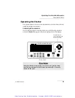
Page 60: ...activated Shutter On appears in the lower right portion of the display CAUTION Using the shutter continuously at a rate of one cycle per three seconds may damage the instrument permanently or serious...

Page 61: ...Artisan Technology Group Quality Instrumentation Guaranteed 888 88 SOURCE www artisantg com...
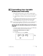
Page 62: ...tely controlled Remote appears in the lower left corner of the display Note If you have already designed a GPIB program to control an attenuator from EXFO s IQ Series IQS 3100 you can reuse sections f...

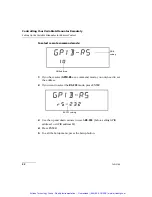
Page 63: ...nd mode you only need to set the address 2 If you want to select the RS 232 mode press ENTER 3 Use the up and down arrows to reach RS 232 before setting GPIB address 1 or GPIB address 30 4 Press ENTER...

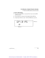
Page 64: ...B address 1 Once you selected GPIB as a command mode you can set the GPIB address you want 2 Press ENTER The bottom part of the displays will start flashing 3 Using the up and down arrows select the G...

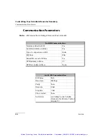
Page 65: ...rites Yes Type of comparison on EOS 8 bits EOS byte 0Ah Sends EOI at end of Writes Yes GPIB primary address 10 GPIB secondary address None For RS 232 Communication EOS bytes 0Ah Baud rate 9600 bps Par...

Page 66: ...ter STB Service Request Enable Register SRE Bit ESR ESE STB SRE 0 Operation Complete Operation Complete Source Status Source Status 1 Request Control Request Control 2 Query Error Query Error Error Bi...

Page 67: ...te Register STB Service Request Enable Register SRE 7 6 5 4 3 2 1 0 7 6 5 4 3 2 1 0 7 6 5 4 3 2 1 0 7 5 4 3 2 1 0 ESB MAV EB ESB MAV RQS 6 MSS Service Request Generation Output Queue not Empty read by...

Page 68: ...UTP STAT wsp boolean is used to control the FVA 3100 shutter In this particular example OUTP identifies that the command is a part of the OUTPut subset of commands STAT is a keyword that defines the f...

Page 69: ...ice dependent information All error messages are stacked in a FIFO buffer When there is at least one message in the buffer bit 2 of the Status Byte Register is set to 1 Use the SYST ERR ERR or LERR co...

Page 70: ...Dependent Error A command has taken longer than expected to complete execution 300 Invalid Attenuation A command has attempted to set the internal attenuation to an invalid value 300 Invalid Offset Th...

Page 71: ...parameter is out of range 300 Invalid Program Attenuation The entered program attenuation parameter is out of range 400 Query Error An error occurred while accessing the output queue 500 System Error...

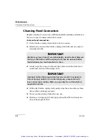
Page 72: ...FVA 3100 Variable Attenuator regularly to avoid buildup of dust dirt and other foreign substances To clean the front panel 1 Gently wipe the front panel with a cloth dampened with soapy water 2 Rinse...

Page 73: ...cal connector baseplate and ferrule 2 Use a lint free wiping cloth and deposit only one drop of isopropyl alcohol on it IMPORTANT If any damage occurs to internal connectors the module casing will hav...

Page 74: ...is not active verify the surface of the connector with a small portable fiber optic microscope IMPORTANT Isopropyl alcohol takes approximately ten seconds to evaporate Since isopropyl alcohol is not...

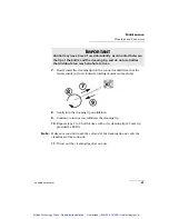
Page 75: ...l alcohol 3 Slowly insert the cleaning tip into the adapter until it comes out on the other side a slow clockwise rotating movement may help IMPORTANT Alcohol may leave traces if used abundantly Avoid...

Page 76: ...draw the cleaning tip 6 Repeat steps 3 to 5 but this time with a dry cleaning tip 2 5 mm tip provided by EXFO Note Make sure you don t touch the soft end of the cleaning tip and verify the cleanliness...

Page 77: ...h gently wipe the same surfaces three times with a rotating movement 5 Throw out the wiping cloths after one use 6 Moisten a cleaning tip 2 5 mm tip provided by EXFO with only one drop of isopropyl al...

Page 78: ...to 9 but this time with a dry cleaning tip 2 5 mm tip provided by EXFO Note Make sure you don t touch the soft end of the cleaning tip and verify the cleanliness of the cotton tip 11 Throw out the cle...

Page 79: ...ng tip on the detector window 6 Repeat previous step but this time with a dry cleaning tip or blow dry with compressed air 7 Discard the cleaning tips after one use IMPORTANT To help keep the detector...

Page 80: ...formity with the ISO IEC 17025 Standard EXFO recommends that an annual calibration be performed on your FVA 3100 Variable Attenuator to ensure that it remains within the published specifications Howev...

Page 81: ...Artisan Technology Group Quality Instrumentation Guaranteed 888 88 SOURCE www artisantg com...
Page 82: ...em XX To access FAQs 1 Type the following address in your Internet browser www exfo com 2 Click on the Support tab 3 Click on FAQs and follow the on screen instructions You will be given a list of que...

Page 83: ...lease have information such as the name and the serial number of your product see the product identification label shown below as well as a description of your problem close at hand Technical Support...

Page 84: ...from improper handling The following steps are recommended to minimize the possibility of damage Pack the unit in its original packing material when shipping Avoid high humidity or large temperature f...

Page 85: ...Artisan Technology Group Quality Instrumentation Guaranteed 888 88 SOURCE www artisantg com...
Page 86: ...L OTHER WARRANTIES EXPRESSED IMPLIED OR STATUTORY INCLUDING BUT NOT LIMITED TO THE IMPLIED WARRANTIES OF MERCHANTABILITY AND FITNESS FOR A PARTICULAR PURPOSE IN NO EVENT SHALL EXFO BE LIABLE FOR SPECI...

Page 87: ...ification of the product its accompanying accessories and software Exclusions EXFO reserves the right to make changes in the design or construction of any of its products at any time without incurring...

Page 88: ...ack the equipment in its original shipping material Be sure to include a statement or report fully detailing the defect and the conditions under which it was observed 5 Return the equipment prepaid to...

Page 89: ...85 85 Fax 33 1 40 83 04 42 europe service exfo com EXFO China Service Center Beijing OSIC Beijing New Century Hotel Office Tower Room 1754 1755 No 6 Southern Capital Gym Road Beijing 100044 P R CHINA...

Page 90: ...F Relative humiditya a Measured in 0 C to 31 C 32 F to 87 8 F range decreasing linearly to 50 at 40 C 104 F 0 to 80 non condensing Maximum operation altitude 2000 m 6562 ft Pollution degree 2 Installa...

Page 91: ...nm to 1590 nm 70 1400 nm to 1600 nm 70 1510 nm to 1590 nm 70 1600 nm to 1650 nm 65 1600 nm to 1650 nm Insertion loss3 4 dB Typical 1 5 3 0 1 5 2 0 Maximum 1 8 3 3 1 8 3 0 Resolution dB 0 005 0 005 0 0...

Page 92: ...status command ESE Standard event status enable command ESE Standard event status enable query ESR Standard event status register query IDN Identification query OPC Operation complete command OPC Ope...

Page 93: ...e the same result ESE Description This command is used to set bits in the Standard Event Status Enable Register ESE to a new value default value is 255 The contents of the ESE register are logically A...

Page 94: ...sponse EXFO E O Engineering FVA 3100 Vxx xx where xx xx is the current product version Note The SYST VERS and IDN commands are equivalent to the IDN command They give the same result OPC Description T...

Page 95: ...ommand after IDN you will not be able to access the answer The RST in this instance erases the identification string In addition this command performs the following operations Returns to initial state...

Page 96: ...x SRE wsp value Parameter The value parameter must be between 0 and 255 SRE Description This query returns the contents of the Service Request Enable Register Syntax SRE Response Binary integer betwee...

Page 97: ...e indicating the results of the test Syntax TST Response A binary value 0 if the test is completed without error 1 if the test is completed with errors WAI Description This command prevents the FVA 31...

Page 98: ...no external input can interfere with the GPIB communication The only way to unlock the keypad is to use the LOK command again or turn off the unit Syntax LOK wsp data Parameters The data parameter can...

Page 99: ...he FVA 3100 keypad lock state Syntax LOK Response 1 if the FVA 3100 keypad is locked 0 if the FVA 3100 keypad is unlocked Example LOK Note This command can only be used when working with RS 232 commun...

Page 100: ...ctivate shutter D 0 1 obtain shutter state DISP DIMM LO HI OFF adjust display intensity DIMM LO HI OFF obtain display intensity Fa b 1 2 set fiber type F 1 2 obtain fiber type INP ATTa 99 99 DB MIN MA...

Page 101: ...n shutter state PROG SEL ATT 99 99 set atten parameter DELA 999 59 59 set delay parameter DURA 999 59 59 set duration parameter STAT 0 1 START STOP control the program STAT 0 1 obtain program state ST...

Page 102: ...nuation to a specific value The valid range of values depends on the configuration of the FVA 3100 and on the current wavelength The resolution of the value is 0 005 dB for singlemode models and 0 01...

Page 103: ...ent values In Absolute mode In Reference mode In Offset mode Therefore when in Reference or Offset mode the range of the accepted values for the value parameter will change according to the current re...

Page 104: ...ent wavelength Response The attenuation value in the format 999 99 The units are dB Note that depending on the current measurement mode the response will include different parameters In Absolute mode...

Page 105: ...rameters The value parameter must be a valid attenuation value in the format 99 999 The units DB are optional Example CAL 99 999 DB CAL Description This query returns the offset value that is applied...

Page 106: ...he shutter Example D 1 Note This command cannot be issued while a program is running The D command is similar to the OUTP STAT command D Description This query returns the current shutter state Syntax...

Page 107: ...Note When the display is turned off by this command any key pressed on the FVA 3100 keypad will return the display to high intensity To prevent this lock the FVA 3100 keypad with the LOK command See...

Page 108: ...no effect on the FVA 3100 The FVA 3100 is designed to test either singlemode or multimode fiber but not both Fiber Description This query returns the type of fiber singlemode or multimode that the FVA...

Page 109: ...ion to a specific value The valid range of values depends on the configuration of the FVA 3100 and on the current wavelength The resolution of the value is 0 005 dB for singlemode models and 0 01 dB f...

Page 110: ...ferent values In Absolute mode In Reference mode In Offset mode Therefore when in Reference or Offset mode the range of the accepted values for the value parameter will change according to the current...

Page 111: ...ent wavelength MAX to obtain the maximum setting for the current wavelength Response The attenuation value in the format 999 99 The units are dB Note that depending on the current measurement mode the...

Page 112: ...value followed by the optional units dB Example INP OFFS 99 99 DB Note This command cannot be issued while a program is running INPut OFFSet DISPlay Description This command sets the reference value...

Page 113: ...ettings Use the INP STEP CATA query to obtain the list of available step sizes If the requested step is not available the FVA 3100 is set to the next available step If the requested step is greater th...

Page 114: ...P STEP INPut STEP CATAlog Description This query returns the list of available step sizes between two attenuation settings Use this command to determine the maximum resolution of the attenuation or re...

Page 115: ...INP WAVE command is equivalent to the WVL command Both give the same result INPut WAVElength Description This query returns a value indicating the currently selected wavelength the minimum available...

Page 116: ...uation is relative to the reference Syntax OUTP APM wsp boolean Parameters The boolean parameter can be 0 or OFF to select Reference display mode 1 or ON to select Absolute display mode Example OUTP A...

Page 117: ...to optically open the shutter Example OUTP STAT ON Note This command cannot be issued while a program is running The OUTP STAT command is similar to the D command OUTPut STATe Description This query r...

Page 118: ...dB The units are optional Example PROG SEL ATT 3 Note This command cannot be issued while a program is running PROGram SELected DELAy Description This command changes the delay parameter for the atten...

Page 119: ...step This value has the following format 999 59 59 hours minutes seconds Example PROG SEL DURA 000 10 00 Note This command cannot be issued while a program is running PROGram SELected STATe Descripti...

Page 120: ...G SEL STAT PROGram SELected STEP Description This command changes the number of steps parameter for the attenuation program Syntax PROG SEL STEP wsp step Parameters The step parameter is the number of...

Page 121: ...command is equivalent to the INP WAVE command Both give the same result WaVeLength Description This query returns a value indicating the currently selected wavelength the minimum available wavelength...

Page 122: ...cessed with the commands SYST ERR ERR or LERR Syntax SYST ERR Response See error list and descriptions in Error Messages on page 58 SYSTem VERSion Description This command returns the FVA 3100 identif...

Page 123: ...Artisan Technology Group Quality Instrumentation Guaranteed 888 88 SOURCE www artisantg com...
Page 124: ...C calibration certificate 69 due date 69 label 69 Canadian Standards Association CSA v caution 14 of personal hazard 7 of product hazard 7 certification information v cleaning connectors with EUI EUA...

Page 125: ...t port 2 installing bentchtop in a rackmount 12 installing rackmount 11 intensity of the display 15 IQ Series 51 K keypad lockout 17 to lock 17 to unlock 18 L label identification 72 locking control k...

Page 126: ...on 60 S safety caution 7 conventions 7 warning 7 saving a configuration 35 self test 13 serial port 60 service and repairs 77 service centers 78 setting display intensity 15 the attenuation 23 the FVA...

Page 127: ...spectral tuning 4 U unit recalibration 69 W warranty certification 76 exclusions 76 general 75 liability 76 null and void 75 wavelength setting 19 see also shortlist of wavelengths wavelength correcti...

Page 128: ...uipment Have surplus equipment taking up shelf space We ll give it a new home Learn more Visit us at artisantg com for more info on price quotes drivers technical specifications manuals and documentat...

Reviews: