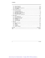
F
IGURES
Loss Test Set
v
F
IGURES
Figure 1-1.
Laser Warning Label ........................................................................................1-3
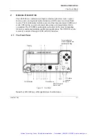
Figure 2-1.
Front Panel .......................................................................................................2-1
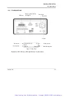
Figure 2-2.
Back Panel .......................................................................................................2-3
Figure 2-3.
RS-232 Connector Pinout ................................................................................2-4
Figure 3-1.
Display in Absolute Mode .................................................................................3-2
Figure 3-2.
Display in Relative Mode (units of dB) .............................................................3-4
Figure 3-3.
Display in Relative Mode (units of watts) .........................................................3-4
Figure 3-4.
Current Reference Value (Selected Wavelength and Unit) ..............................3-6
Figure 3-5.
Display with a 1310-nm Source Activated in CW .............................................3-7
Figure 3-6.
Display in ORL Mode .......................................................................................3-8
Figure 3-7.
Display with the VFL Activated in CW ............................................................3-12
Figure 4-1.
Menu Diagram ..................................................................................................4-1
Figure 4-2.
Starting an Acquisition .....................................................................................4-7
Figure 5-1.
LTS-3900 Label Printing Utility Window ...........................................................5-3
Figure 5-2.
Crystal Reports–Insert Fields Window .............................................................5-6
Figure 6-1.
Standard Status Data Structures (IEEE 488.2) ................................................6-4
Figure 6-2.
Error Message Format ...................................................................................6-35
Figure 8-1.
Pulling out the Fuse Holder ..............................................................................8-3
Figure 8-2.
Replacing the Fuses ........................................................................................8-3
Artisan Technology Group - Quality Instrumentation ... Guaranteed | (888) 88-SOURCE | www.artisantg.com


