W2CM-10Gb Ethernet Interface Series
QualityAssurer 805
27
Module Installation
6.
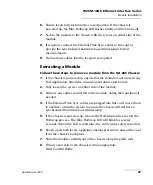
Ensure levers fully lock into the closed position. If the chassis is
powered up, the Blue HotSwap LED flashes briefly and then turns off.
7.
Secure the module to the chassis with the screws on either side of the
module.
8.
If required, connect the External Time Sync cables to the card to
provide the synchronized hardware based timestamps for test
measurements.
9.
Re-insert any cables into the test-port as required.
Extracting a Module
Follow these steps to remove a module from the QA-805 Chassis:
1.
If the chassis is powered up, ensure that the module is not in use in any
Test Application, otherwise measurement data could be lost.
2.
Fully loosen the screws on either side of the module.
3.
Remove any cables connected to the module, noting their positions if
needed.
4.
If the External Time Sync cables are plugged into this card, move them
to another card in the system to ensure the chassis will still have a
synchronized hardware based timestamp.
5.
If the chassis is powered up, release the HotSwap latches to start the
HotSwap process. The Blue HotSwap LED will blink for several
seconds. When the LED is solid blue, the card can be safely extracted.
6.
Slowly open both levers, applying constant pressure to unseat the card
from the chassis's backplane.
7.
Slide the module carefully out of the chassis along the guide rails.
8.
Fill any open slots in the chassis with an appropriate
Filler Card/Air Baffle.
Summary of Contents for Quality Assurer QA-604
Page 1: ...User Guide QA 805 and W2 CM Interface Module...
Page 8: ......
Page 30: ......
Page 44: ......
Page 52: ......

