Summary of Contents for Quality Assurer QA-604

Page 1: ...User Guide QA 805 and W2 CM Interface Module...

Page 2: ...for any infringements of patents or other rights of third parties that may result from its use No license is granted by implication or otherwise under any patent rights of EXFO EXFO s Commerce And Gov...

Page 3: ...utions 18 Installation Instruction Warnings 19 Equipment Ratings 21 3 Getting Started 23 Shelf Installation 23 Turning the Unit On Off 23 4 W2CM 10Gb Ethernet Interface Series 25 Module Installation 2...

Page 4: ...nty 39 General Information 39 Liability 40 Exclusions 41 Certification 41 Service and Repairs 42 EXFO Service Centers Worldwide 43 43 A Technical Specifications 45 QualityAssurer QA 805 45 W2CM 10 Gig...

Page 5: ...designed to provide reasonable protection against harmful interference when the equipment is operated in a commercial environment This equipment generates uses and can radiate radio frequency energy a...

Page 6: ...246810 Equipment Type Environment Test Measurement Industrial Trade Name Model No Next Generation Network Test Platform Quality Assurer QA 805 Standard s to which Conformity is declared EN 60950 1 20...

Page 7: ...rement Basic Trade Name Model No 10 Gigabit Ethernet Interface Series W 2 CM Standard s to which Conformity is declared EN 60950 1 2006 A11 2009 2nd Edition Information Technology Equipment Safety Par...

Page 8: ......

Page 9: ...The QA 805 offers easy to use test solutions covering the complete testing life cycle of LTE IMS VoLTE and VoIP networks and services QA 805 Features Six unit rack mounted Emulation of over 5 million...

Page 10: ...ce Module Front View of QA 805 Front View of QA 805 This image of the QA 805 chassis provides a realistic view of the front panel See the section Chassis Front Panel on page 4 for further details that...

Page 11: ...r 805 3 Rear View of QA 805 Rear View of QA 805 This image of the rear panel on the QA 805 provides a realistic view of the back of the chassis See the section Chassis Back Panel on page 5 for details...

Page 12: ...icture of the front of the QA 805 rack mount model 1 Right Fan Tray FT1 2 Left Fan Tray FT2 3 Power supplies cover and air filter holder 4 Control Board Slot 2 SHMC2 not populated 5 Control Board Slot...

Page 13: ...12 Power supply unit slot 4 Chassis Back Panel The following is a picture of the back of the QA 805 chassis 13 Shelf Ground Terminals 14 Individual Power Switch for each power supply 15 Individual AC...

Page 14: ...wer and high speed links are routed on the same stack up The backplane supports the following 6 AdvancedTCA front board slots 6 AdvancedTCA RTM Rear Transmission Module slots 2 fan trays 4 power suppl...

Page 15: ...ow voltage electronics and is isolated from the chassis shelf ground and 48 V power lines For EMI EMC purposes it might be needed to connect the logic ground and shelf ground together To connect both...

Page 16: ...Introduction 8 QA 805 and W2CM Interface Module Physical Description of QA 805 Unit Note The screw is installed by default...

Page 17: ...ising and control circuitry The system utilizes push pull cooling with 2 separately managed fan trays and 4 independent cooling zones Integrated power supplies enable using 48 V fans without any degra...

Page 18: ...ve the head to the left or right away from the fan tray 2 Hold the head while pulling out the fan tray using the handle To insert the fan tray 1 Loosen the locking mechanism and move the head to the l...

Page 19: ...before fully removing CAUTION Electrostatic Discharge ESD Sensitive Equipment To avoid damage due to electrostatic discharge all removable cards must be stored and handled using approved ESD protectiv...

Page 20: ...Filtration of intake air from dust particles Additional static pressure to achieve uniform airflow Air filter frame is mounted on the right fan tray cassette To change the air filter 1 Extract the fan...

Page 21: ...55022 Class B FCC Part 15 Active PFC 0 99 Hot swappable Power supply present and power OK sensors Bi colour LED indicates Power OK CAUTION Internal fusing Input voltage to this unit is classified as h...

Page 22: ...power supply a separate AC inlet as well as switch is provided Use power cords rated for currents which exceed the maximum power supply current CAUTION When working near the power supply power inlets...

Page 23: ...trays 466 15 mm 18 35 in Power Specification 4 slots for redundant hot swappable power supplies 850 W power supply at low line 90 V and high line 264 V 2N and N 1 with additional bridge board redunda...

Page 24: ...oceed unless you understand and meet the required conditions CAUTION Indicates a potentially hazardous situation which if not avoided may result in minor or moderate injury Do not proceed unless you u...

Page 25: ...ibers while a light source is active Never look directly into a live fiber and ensure that your eyes are protected at all times WARNING The use of controls adjustments and procedures other than those...

Page 26: ...lear when servicing Allow time for fan blades to slow to a stop before fully removing CAUTION Electrostatic Discharge ESD Sensitive Equipment To avoid damage due to electrostatic discharge all removab...

Page 27: ...e for the equipment in this environment is 40 C Consideration should be given to the maximum rated ambient 2 Installation should be such that a hazardous stability condition is not achieved due to une...

Page 28: ...tolerant but should only be hot swapped when not in use by an application Cooling To ensure optimum cooling within the chassis all empty slots in the chassis front and back must be filled with the app...

Page 29: ...40 C to 70 C 40 F to 158 F Relative humiditya a Measured in 0 C to 31 C 32 F to 87 8 F range decreasing linearly to 50 at 40 C 104 F 95 non condensing Maximum operation altitude 2000 m 6562 ft Pollut...

Page 30: ......

Page 31: ...propriate protective bonding conductor according to over current limits for power lines 5 Make sure that personnel will not interfere with cables and cords connected to the rack shelf 6 Make sure that...

Page 32: ...ndicate that the System Controller has shut down safely 3 Power down the Hard Drive AM4500 by pulling out the HotSwap switch Wait until the Blue HotSwap LED stops flashing and turns Solid Blue to indi...

Page 33: ...SBC CSCFs BGF HSS and IMS application servers With EXFO s QA 805 the W2 CM 10GbE W2 CM 10GbE Lite and W2 CM 4GbE modules can emulate tens of millions of subscribers generating real world traffic towa...

Page 34: ...ired to provide space for the module being inserted 2 Before inserting the card ensure that the levers on either side of the card are in the fully open position perpendicular to the faceplate 3 Align...

Page 35: ...n use in any Test Application otherwise measurement data could be lost 2 Fully loosen the screws on either side of the module 3 Remove any cables connected to the module noting their positions if need...

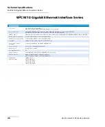
Page 36: ...er optical or copper plugable SFPs Neither copper nor optical SFPs have built in LEDs consequently two LEDs per SFP are positioned right beside each SFP cage LED definition for 10 100 1000 M copper SF...

Page 37: ...eration and integrates a Marvell s PHY 88E1111 The FCLF8520P2BTL uses the SFP s RX_LOS pin for link indication while 1000BASE X auto negotiation should be disabled on the host system LED Label Color D...

Page 38: ...LC connector EXFO Product Transceivers Finisar Output Power dBm Rx Sensitivity dBm SFP Specs FTB 8590 FTLF8519P2BNL 1000BASE SX Multi rate GigE 1xFC 2xFC MIN 9 MAX 3 GigE MIN n a MAX 20 850 nm SR 500...

Page 39: ...r are supported Optical SFP with LC Connector EXFO Product Transceivers Finisar Output Power dBm Rx Sensitivity dBm SFP Specs FTB 8690 FTLX8571D3BCL Multi rate 9 95 10 3 Gbit s 10GBASE SR SW MIN 5 MAX...

Page 40: ...inition for 10 G optical SFP LED Label Color Definition 1 Activity Off Idle Green Unidirectional Activity RX Yellow Bidirectional Activity Red Unidirectional Activity TX LED Label Color Definition 2 L...

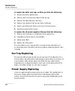
Page 41: ...unit dry completely Maintaining Air Filters Due to the environment the system operates in the filters will accumulate dust causing a degradation in filtration and airflow to the system Therefore the...

Page 42: ...ilter 4 Replace the front panel The old air filter can be cleaned with a vacuum cleaner but this is not recommended since the filter will never regain its original properties after cleaning Fan Tray R...

Page 43: ...cling and Disposal Applies to European Union Only Recycling and Disposal Applies to European Union Only For complete recycling disposal information as per European Directive WEEE 2012 19 UE visit the...

Page 44: ......

Page 45: ...t the EXFO Web site at www exfo com For detailed information about technical support and for a list of other worldwide locations visit the EXFO Web site at www exfo com To accelerate the process pleas...

Page 46: ...rtation damage can occur from improper handling The following steps are recommended to minimize the possibility of damage Pack the unit in its original packing material when shipping Ensure all cards...

Page 47: ...n during the warranty period and found to meet all published specifications EXFO will charge standard calibration fees THIS WARRANTY IS IN LIEU OF ALL OTHER WARRANTIES EXPRESSED IMPLIED OR STATUTORY I...

Page 48: ...oduct nor shall be responsible for any failure in the performance of other items to which the product is connected or the operation of any system of which the product may be a part EXFO shall not be l...

Page 49: ...are not covered by this warranty This warranty excludes failure resulting from improper use or installation normal wear and tear accident abuse neglect fire water lightning or other acts of nature ca...

Page 50: ...and the conditions under which it was observed 5 Return the equipment prepaid to the address given to you by support personnel Be sure to write the RMA number on the shipping slip EXFO will refuse and...

Page 51: ...USA and Canada Tel 1 418 683 5498 Fax 1 418 683 9224 support exfo com EXFO Europe Service Center Winchester House School Lane Chandlers Ford Hampshire S053 4DG ENGLAND Tel 44 2380 246800 Fax 44 2380...

Page 52: ......

Page 53: ...latform per interface or per port hardware or software Interfaces USB DP Ethernet management USB DP Ethernet management USB 2 VGA Ethernet management Operating system Linux Linux Solaris Processor and...

Page 54: ...264 DTMF SIP LTE endpoints per module 2 million W2 CM 10GbE 1 million W2 CM 10GbE Lite Number of sessions per module 2 million W2 CM 10GbE 1 million W2 CM 10GbE Lite Throughput 20 Gbit s W2 CM 10GbE...

Page 55: ...label identification 37 M maintenance front panel 33 general information 33 maximum input current 21 P power source AC 21 product identification label 37 specifications 45 R return merchandise author...

Page 56: ...Index 48 QA 805 and W2CM Interface Module W warranty certification 41 exclusions 41 general 39 liability 40 null and void 39...

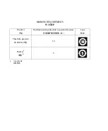
Page 57: ...chanical sub assemblya a O O O O O O MARKING REQUIREMENTS Product Environmental protection use period years Logo his Exfo product EXFO 10 Batterya a f applicable 5 NOTICE CHINESE REGULATION ON RESTRIC...

Page 58: ...MARKING REQUIREMENTS Product Environmental protection use period years Logo This Exfo product EXFO 10 Batterya a a If applicable 5...

Page 59: ...EXFO ASIA PACIFIC 100 Beach Road 25 01 03 Shaw Tower SINGAPORE 189702 Tel 65 6333 8241 Fax 65 6333 8242 EXFO CHINA Beijing Global Trade Center Tower C Room 1207 36 North Third Ring Road East Dongchen...

Reviews: