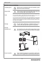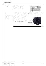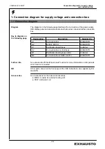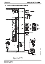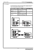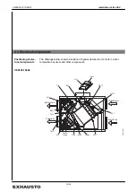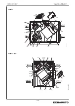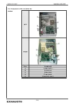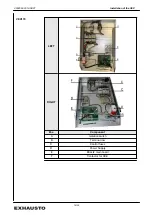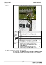
Diagram
The supply voltage must be connected to the isolation switch as shown in the dia-
gram in section 1.
2.2.1 Installation requirements and recommendations
Isolation switch and
control fuses
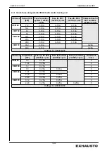
An isolation switch and control fuses have been integrated in the unit. The control
fuses protect internal electrical components from overload and short-circuiting. The
section "Control fuses" indicates the number and size of integrated control fuses.
Fuses
The fuses must be suitable for:
●
Short-circuit protection of the unit
●
Short-circuit protection of the supply cable
●
Overload protection of the supply cable
Max. rating
Maximum fuse rating is
●
VEX140-150-160 : 63 A (gG/gL).
●
VEX170: 100 A (gG/gL).
Power supply cable
When dimensioning the supply cable, the conditions at the installation location, in-
cluding temperature and cable duct layout, must be taken into consideration.
Earth leak circuit
breaker
●
The unit must be protected against indirect contact.
If current earth leak circuit breakers are fitted in the installation, they must be
of a type that meets the following requirements:
VEX140-150-160:
PFI type A breaker that breaks the circuit on registering a vagrant
current with DC content (pulsating DC) in accordance with EN
61008.
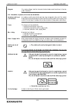
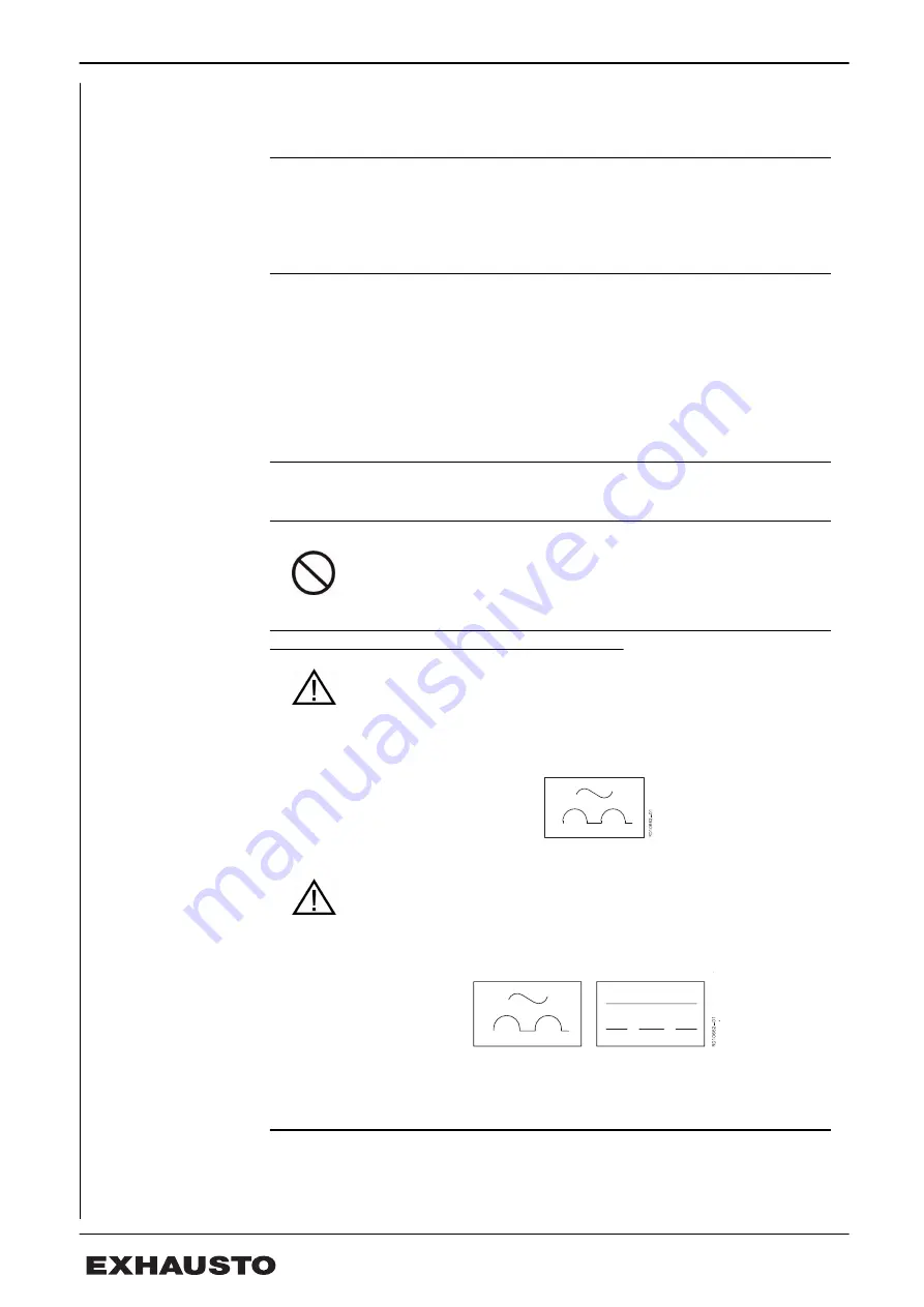
The circuit breakers must be marked with the following symbol:
VEX170:
PFI type B breaker that breaks the circuit on registering a vagrant
current with DC content (pulsating DC) or smooth vagrant current
in accordance with EN 61008.
The circuit breakers must be marked with the following symbol:
●
Cutout time must be max. 0.3 s.
Current leakage
A leak current of up to 100 mA can be generated.
3004524-2014-08-27
Installation of the VEX
10/24


