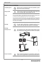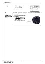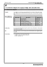
2. Installation of the VEX
2.1 Scope of installation
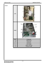
VEX unit
The electrical installation for the VEX unit comprises the following connections:
Connection to VEX unit:
●
Connection box
●
MXCU module for external cooling coil (if any)
●
CCW cold water coil (if any)
2.1.1 Connections in the connection box
Wiring configura-
tions
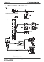
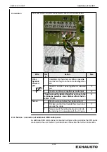
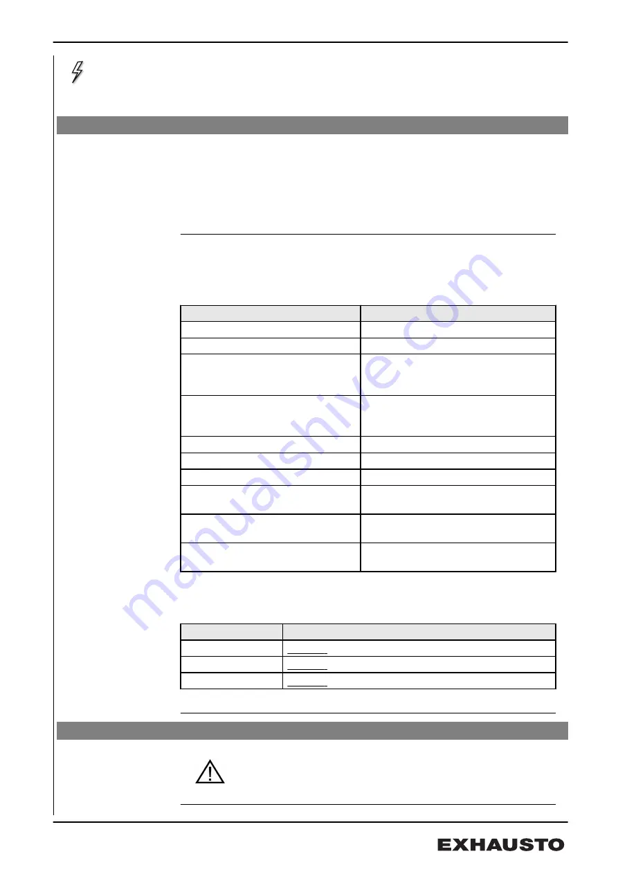
Wiring configurations for the terminal board in the connection box are shown in the
table below.
Wiring configurations
See section
Supply voltage
2.2
HMI control panel via modbus
1
MODBUS components, via MODBUS
1
on termination and instructions for the
component in question
Control for external MXCU cooling
unit
1
on termination and instructions for the
MXCU module
Control for cold water coil MCCW
in the cold water coil CCW instructions
External start*
below
Circulation pump
1
Closing damper, exhaust air LSA/
LSAR
1
Outdoor air closing damper LSF/
LSFR
1
Fire and AUX IN*
1
and below
* External start, Fire
and AUX IN
Note following jumper settings for EXact2 main board
If
Then
Fire is used
remove
the jumper between terminals 20 and 21
AUX IN is used
remove
the jumper between terminals 22 and 23
EXT start is used
remove
the jumper between terminals 24 and 25
2.2 Dimensioning and electrical installation
●
The supply cable must be dimensioned and installed in ac-
cordance with applicable rules and regulations.
●
The earth terminal (PE) must always be connected.
3004524-2014-08-27
Installation of the VEX
9/24


