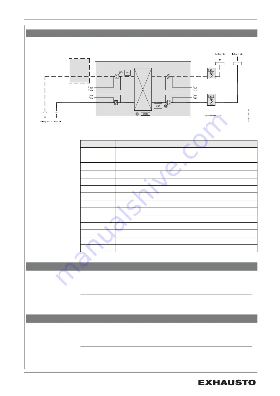
1.2 Designations used in these instructions
1.2.1 Designations used in these instructions
The simplified diagram shows a VEX unit with fan location 1, Left
Component
Function
MC1
Motor control, motor 1 (extract air)
MC2
Motor control, motor 2 (supply air)
LS
1)
Closing damper, outdoor air/exhaust air
M1
Fan motor 1
M2
Fan motor 2
DRHX
Control unit for the rotary heat exchanger
P1.1X
Measurement point, pressure drop across extract air filter
P1.1Y
Measurement point, pressure drop across extract air filter
P1.2X
Measurement point, airflow in exhaust air
P1.2Y
Measurement point, airflow in exhaust air
P2.1X
Measurement point, pressure drop across outdoor air filter
P2.1Y
Measurement point, pressure drop across outdoor air filter
P2.2X
Measurement point, airflow in supply air
P2.2Y
Measurement point, airflow in supply air
1.3 Application
Comfort ventilation
EXHAUSTO VEX is used for comfort ventilation tasks. Operating temperature
range for the unit – see section "Technical data".
Prohibited uses
The VEX unit is not to be used to transport solid particles or in areas where there
is a risk of explosive gases.
1.4 Location requirements
Positioning
The air handling unit is designed for indoor fitting. The air handling unit can be or-
dered for outdoor installation (accessory Outdoor, OD).
3005039-2018-01-08
Product information
7/32
Summary of Contents for VEX200 series
Page 23: ...Supply air Supply airflow diagram 3005039 2018 01 08 Maintenance 23 32...
Page 24: ...Extract air Extract airflow diagram 3005039 2018 01 08 Maintenance 24 32...
Page 29: ...3005039 2018 01 08 29 32...
Page 30: ...3005039 2018 01 08 30 32...
Page 31: ...3005039 2018 01 08 31 32...
Page 32: ......


