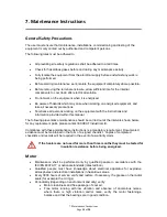
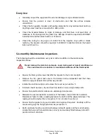
EXHeat MFH T3, Installation, Operation & Maintenance Instructions Manual
The EXHeat MFH T3 manual provides comprehensive Installation, Operation & Maintenance Instructions for easy setup and upkeep of your heating system. Download the manual for free from 88.208.23.73:8080 to ensure optimal performance and longevity of your product. Simplify the process with detailed guidance at your fingertips.
Share
Download


Reviews:
No comments
Related manuals for MFH T3

7937
Brand: Sage Pages: 8
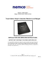
9100A
Brand: Nemco Pages: 12
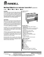
3612
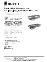
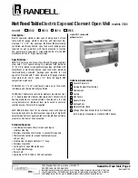
Brand: Randell Pages: 2
SR-DF101
Brand: Panasonic Pages: 41
Infinity
Brand: WarmlyYours Pages: 13
A120465
Brand: Bartscher Pages: 84
WT-100
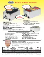
Brand: Cadco Pages: 2
DWW-11
Brand: Cadco Pages: 1

BS 22
Brand: H+H Pages: 32

FOOT WARMER
Brand: Lanaform Pages: 64
9560-1
Brand: Randell Pages: 2
3512
Brand: Randell Pages: 2
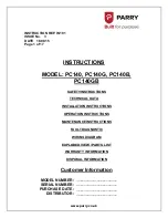
PC140
Brand: PARRY Pages: 17
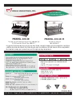
282-24
Brand: Wisco Industries Pages: 7
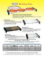
WT-10S
Brand: Cadco Pages: 2

MINI DIPPER RJ15-065-R
Brand: Chefman Pages: 12
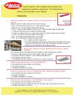
Glo-Ray GRAH-24
Brand: Hatco Pages: 3
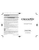
LITTLE DIPPER WARMER
Brand: Crock-Pot Pages: 4


