


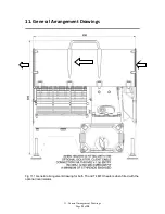
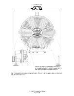

5. Installation Instructions
Page
9
of
28
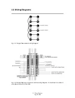
Electrical Supply Connection with Optional Local Isolator fitted.
•
Refer to the wiring diagram in Section 12.
•
Cable entry to the optional local isolator is via 1 off pre drilled M32x1.5p hole and
fitted with a temporary plastic plug. Remove the plug and install the cable and gland
as per manufacturer’s instructions.
•
Connect the Live connection(s), Neutral and Earth in accordance with the appropriate
wiring diagram in Section 12.
•
The Live and Neutral connections to the heaters are made using the installed
terminals and by the use of proprietary ferrule crimps (client supplied). The isolator
can accept a maximum cable size of 25mm². Torque to 2N.m.
•
Optionally, the external earth connection is made by use of proprietary ring crimps to
suit an M6 fixing and to suit the size of cable installed. This is found adjacent to the
cable entries.
•
With the connections made, replace the enclosure lids securely with all fasteners.
•
When replacing the Isolator, ensure the cable is looped around the bracket to prevent
snagging.
Electrical Supply Connection without Optional Local Isolator fitted.
•
Refer to the wiring diagram in Section 12.
•
Cable entry to the main terminal enclosure is via 1 off M20 Certified cable gland (not
supplied).
•
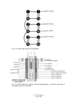
Connect the live connection(s), neutral and earth in accordance with the appropriate
wiring diagram in Section 12.
•
The live and neutral connections to the heaters are made using the installed
terminals and by the use of proprietary ferrule crimps (client supplied). The terminals
can accept a maximum cable size of 10mm² and must be tightened to 1.2N.m min /
1.9N.m max.
•
Optionally, the external earth connection is made by use of proprietary ring crimps to
suit an M6 fixing and to suit the size of cable installed. This is found adjacent to the
cable entries.
•
With the connections made, replace the enclosure lids securely with all fasteners to
5N.m min.
Ensure that the connections are made in accordance with site philosophy. If using
ferrules, a minimum of 5.5mm must be engaged within the terminals. If using multi-
stranded cable, the stripping length should be 12mm. No modification to allow other
connections is permitted.
DO NOT ENERGISE THE HEATER AT THIS TIME
DO NOT ENERGISE THE HEATER AT THIS TIME