


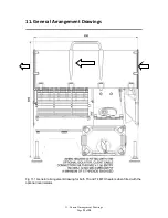
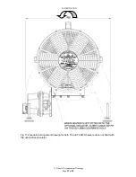

5. Installation Instructions
Page
10
of
28
General Installation Instructions
With the power supply cable connected please complete these remaining instructions before
energising.
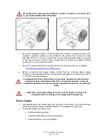
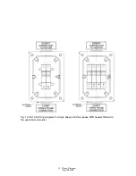
•
Place the heater on its feet in the desired operational location and make further minor
adjustments to each foot as required in order to prevent the heater from rocking.
Failure to do so could cause damage to the heater.
•
Ensure the distance between the Isolator and the ground is at least 40mm at all
times.
•
The installer and the end user shall ensure that the unit has free and unrestricted air
flow to allow natural convection to occur at all times. DO NOT COVER the heater and
do not allow anything to rest on or against it when in operation.
Terminate / connect the power supply end of the power cable to
the isolated power supply or a certified plug as required.
Warnings
•
No additional cable entries are to be made within the terminal box. Only EXHEAT
Industrial Ltd. can facilitate this.
•
No alterations are permitted to the factory installed wiring.
•
The cable glands installed to the MFH heater should be such that they do not
decrease the IIB + H2 rating of the heater. All cable glands are to be suitable for the
rating and size of the supply cables. IP washers are to be used where applicable.
•
Before connection ensure that the supply corresponds with that specified on the
nameplate label, and that the sizes and types of cables to be used are suitably rated
for the load and temperature of the product.
•
Each heater circuit must be protected by a suitably rated over current device and
earth leakage circuit breaker device. See below for earth connection details.
•
The covers of the MFH range terminal boxes are removed by simply un-bolting the lid
fittings. When re-fitting ensure that any gasket seal is in good condition and correctly
located. The main cover mating faces
MUST
be kept clean and free from any debris
at all times.
•
The installer or end user must connect to the EXHEAT Industrial Ltd designated
terminals within the terminal box - DO NOT disturb factory fitted wiring.