background image


With the transmitter turned on and the LiPo 

flight

 battery connected to the ESC 

(and installed in the battery compartment)  it’s  now  possible  to  connect  the  push

rods  to  the  rudder  and  elevator  control  surfaces  and  to ‘center’ the surfaces 

accordingly.  

First, be sure to center the elevator and rudder (aileron) trim levers. See the 

‘Transmitter Details’ and ‘Flight Controls and Trimming’ sections of this manual for 

more information on the trim levers and their functions.

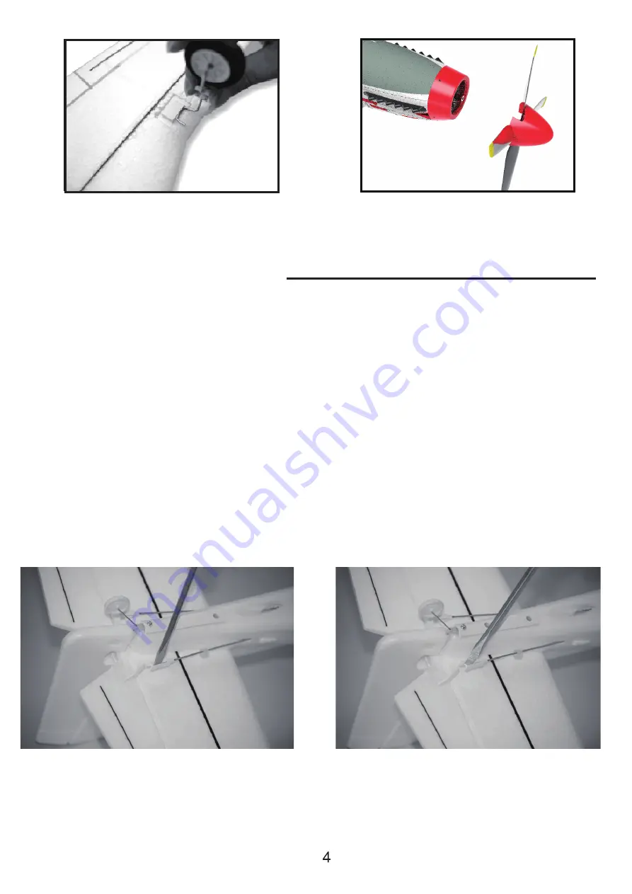
With the trim levers centered, carefully spread open each ‘clevis’ (the white color 

plastic part installed on the threaded end of the metal pushrod) so you can insert 

the pin in the OUTERMOST hole on each control horn. It may  be  helpful  to  insert 

flat

  blade  screwdriver  (not  included)  into  the  clevis  then  carefully  ‘twist’  it  until 

it disengages the pin from the hole in the clevis. Also, it is not necessary to ‘snap’ 

the clevis back together until the centering adjustments are complete.

5. Install the landing gear to the 

gap on the battery cover and fix 

it by screw .

6. Install the propeller with spinner

to the motor shaft.

Center the control surfaces

Summary of Contents for 768-1

Page 1: ...768 1 Mustang P 51D User Manual ...

Page 2: ... for safety operation and maintenance It is essential to read and follow all the instructions and warnings in the manual prior to assembly setup or use in order to operate correctly and avoid damage or serious injury Age Recommendation Not for children under 14 years This is not a toy As the user of this product you are solely responsible for operating in a manner that does not endanger yourself a...

Page 3: ...or 3 3 Install control horns to preserved position on control surfaces 4 Connect the push rod to the servo horn 11 10 9 8 7 6 5 4 3 2 1 1 Main wing 2 Fuselage 3 Horizontal Tail 4 Landing Gear 5 Propeller 6 Spinner 7 Philips Screw Driver 8 Screws bag 9 Radio Transmitter RTF 10 Lithium Battery RTF 11 USB Charger RTF ...

Page 4: ... functions With the trim levers centered carefully spread open each clevis the white color plastic part installed on the threaded end of the metal pushrod so you can insert the pin in the OUTERMOST hole on each control horn It may be helpful to insert a flat blade screwdriver not included into the clevis then carefully twist it until it disengages the pin from the hole in the clevis Also it is not ...

Page 5: ... to one full turn then insert the pin back into the outermost hole in the control horn Or if the rudder is angled off to the right carefully remove the clevis from the control horn and screw it out counter clockwise one half to one full turn then insert the pin back into the outermost hole in the control horn View the vertical tail and rudder from directly above again and continue adjusting the le...

Page 6: ...he way of the model flight If the C G is too far aft tail heavy the model will be too re sponsive and difficult to control If the C G is too far forward nose heavy the model will be too stable and not responsive enough In order to obtain the C G specified add weight to the fuselage or move the battery position Check the C G before flying ...

Page 7: ...s Always transport or temporarily store the battery in a temperature range of 40 120 Fahrenheit degrees 5 49 degrees centigrade Do not store battery or your plane in a car or direct sunlight If stored in a car with high temperature the battery can be damaged or even cause fire Always charge a battery away from flammable materials Always inspect the battery before charging and never charge damaged ...

Page 8: ... the plane steady to activate the gyro 2 Connect the battery to the plane 3 Power on transmitter keep the throttle stick at lowest position 5 Now the plane is bound to the transmitter Throttle Unlock Arming Notice To prevent from damages the throttle channel is locked each time when power on your transmitter Keep the propeller in distance for your safety To unlock the throttle turn the throttle st...

Page 9: ... to see if all servo surfaces react correctly as shown in the left diagram left throttle for example Swing your plane to check if all servo surfaces react correctly as shown in the right diagram Transmitter Operaton Reaction Swing The Plane Reaction Gyro Switch Flight Control Instruction Beginner Strong Flight Control Medium Regular Flight Control Expert Manual Control ...

Page 10: ......

Page 11: ... plane it requires to activate the one key U turn function To use this function during flight press the one key U turn switch button the plane will turn around automatically back to the opposite direction where it takes off To quit just press again the switch button or control any servo stick rudder elevator the plane will back to your control immediately No matter you flies the plane under manual...

Page 12: ... USB port on your computer or USB adapter 3 Connect battery into the charger 4 The charging process takes about 3 5 hours For safety reasons never charge the battery for longer than 4 hours While charging the red LED indicator will be on When charging is finished the red LED will be off NOTE This checklist is NOT intended to replace the content included in this instruction manual Although it can b...

Page 13: ...offs and landings on a smoother surface such Fly in spacious ground w ithout obstacles and boskage tension line c rowed people Flying Area and residential area PLEASE NOTE THE PLANE IS DESIGNED TO BE FLOWN OUTDOORS ONLY crowded neighborhood areas or in areas that are not free of people and obstructions Find a Flight Field your line of sight Flying Conditions ...

Page 14: ...loss of control such as low batteries defective or damaged radio components or radio interference This usually requires an assistant and should be First turn on the transmitter Then install the fully charged battery into the fuselage and hold it in place with the hook and loop strap Connect the battery and install the hatch causing damage or injury With the antenna on the transmitter collapsed not...

Page 15: ...ude cut the motor power The model should establish a gentle downward glide path judge how far out you will need to be when its time to land Flying Make sure that the airplane initiates an ascending glide path If necessary add power to extend the glide path to reach control the glide path and altitude Continue to apply elevator until the mode l touches down at which time you should be holding full ...

Page 16: ...Disconnect the battery and remove it from the airplane Then turn off the transmitter Allow the battery to cool airplane to make sure nothing has become loose or damaged After Flight ...

Reviews: