Exinda Network Orchestrator
2 Getting started
|
19
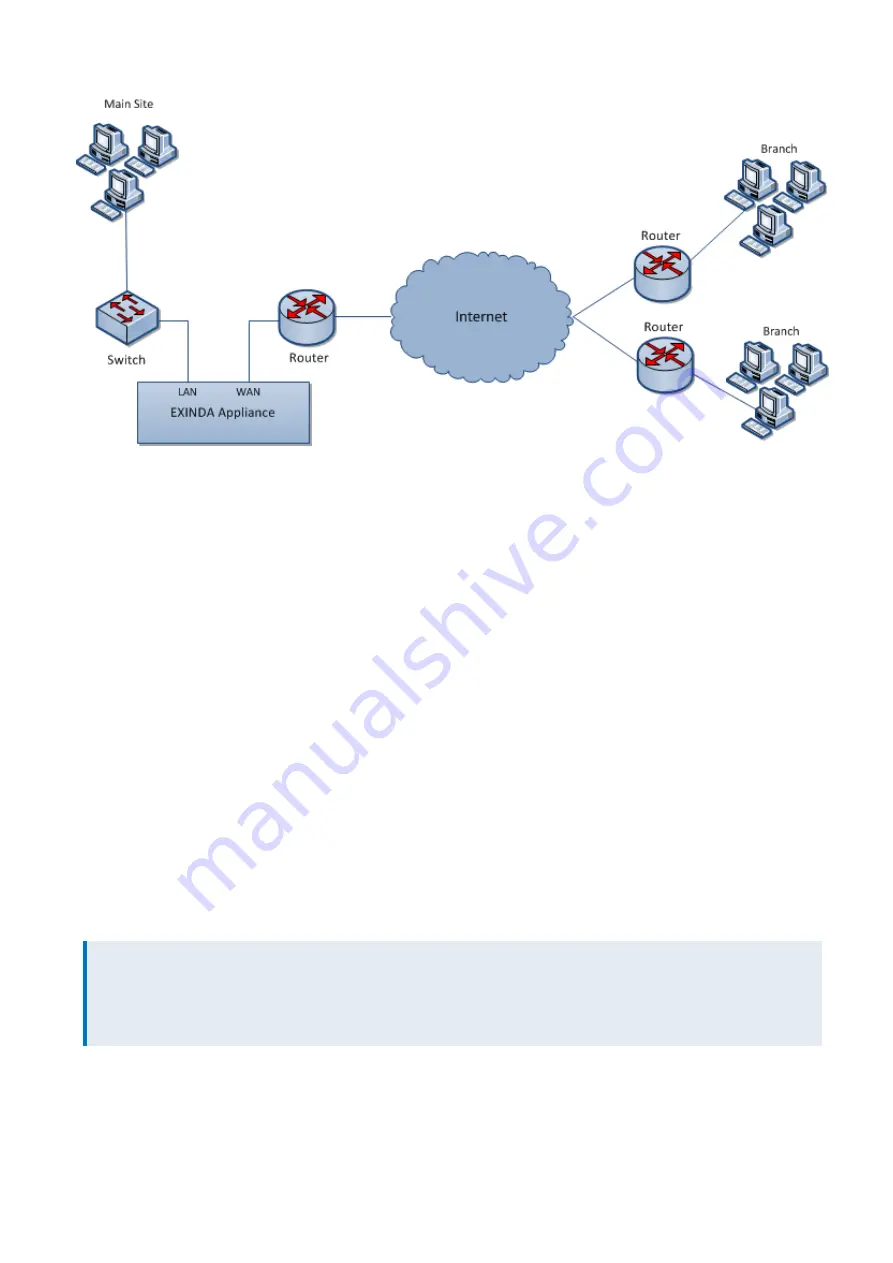
Screenshot 10: Main site internet link deployment
The topology depicted in the diagram shows a basic Exinda Appliance network deployment with several sets of users
from a Main Site and Branch sites linking over the Internet. In Exinda terminology, this general configuration is aptly
named, Main Site Internet Link topology.
The left side of the diagram labeled "Main Site" represents a typical office environment, comprising network users, a
switch, a router and an Exinda Appliance.
The middle of the diagram represents the Internet and the right side of the diagram represents all the people,
machines and programs that want access to servers and applications hosted at the Main Site.
In this setup, the Exinda Appliance is connected to the switch and the router on the Main Site. So network traffic
emanating from the Main Site to the Internet and traffic from the Internet to the Main Site must pass through the Exinda
Appliance.
With the Exinda Appliance deployed between the switch and the router, you get visibility to all the traffic entering and
leaving the Main Site network via the router.
Installing the Exinda Appliance in a main site internet link topology
This install is straightforward and requires just a few steps.
The high level plan is to plug your Exinda Appliance inline between the switch and router.
In most network environments, the switch will already be physically connected to the router. We're going to temporarily
disconnect the switch and router from each other, insert the Exinda Appliance between them and reconnect
everything with the Exinda Appliance firmly in the middle.
NOTE
In network terminology, an "inline" device receives packets and forwards them to their intended destination.
Routers, switches and firewalls are examples of inline devices. The inline designation also alerts you that the device
is critical to network function. If the device goes down, network traffic is affected.
1.
Connect the WAN port to your router/firewall using a crossover cable.
2.
Connect the LAN port to the LAN switch.
3.
Leave the Exinda Appliance powered off.
Summary of Contents for EXNV-10063
Page 369: ...Exinda Network Orchestrator 4 Settings 369 ...
Page 411: ...Exinda Network Orchestrator 4 Settings 411 Screenshot 168 P2P OverflowVirtualCircuit ...
Page 420: ...Exinda Network Orchestrator 4 Settings 420 Screenshot 175 Students OverflowVirtualCircuit ...


