17
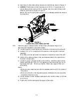
FIGURE 4
PARK BRAKE ADJUSTMENT
3.7 INSTALL SEAT
3.7.1
a) Remove seat assembly from the crate.
b) Remove the four 5/16-18 whizlock nuts from the seat track studs at the
bottom of the seat. Retain for use later.
c) Align the seat track studs on the bottom of the seat with the holes in the
seat frame. Place seat on top of the frame and secure with the four 5/16-18
whizlock nuts remove in step b).
3.8 INSTALL MOTION CONTROL LEVERS
.
3.8.1
Loosen and remove the two (2) 3/8” x 1” bolts and spring disc washers which
attach the motion control levers to the control arm shafts for shipping and the
two (2) 3/8” x 1” bolts and spring disc washers which are screwed into the control
arm shafts.
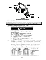
a) Install the left motion control lever onto the control arm shaft (See Figure 5)
on the left side of the console. Place the lever (with the mounting plate
towards the rear) on the
outside
of the control arm shaft and secure with
the bolts and washers. Position the lever so the bolts are in the center of
the slots on the lever mounting plate and tighten until snug. Repeat on
opposite side of unit.
NOTE:
There are two lever height options available. Place the levers in the
top two holes to increase height of the levers, or in the bottom two holes to
decrease the height of the levers.
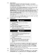
If the levers do not align with each other, when in the neutral position, (See
Figure 6) loosen the hardware and make the appropriate adjustment by
sliding/tilting the lever(s) forward or backward until properly aligned and tighten
hardware.
FIGURE
5
FIGURE
6
CONTROL ARM SHAFT
LEVER ALIGNMENT
MOUNT PLATE TO
THE REAR & OUTSIDE
OF ARM SHAFT
MOTION
CONTROL
LEVER
LEVERS IN
ALIGNMENT
Summary of Contents for Laser Z CT
Page 1: ...For Serial Nos 540 000 Higher Part No 103 9180 ...
Page 45: ...40 8 BRIGGS STRATTON ELECTRICAL DIAGRAM ...
Page 46: ...41 9 HYDRAULIC DIAGRAM ...
Page 48: ... 43 NOTES ...
Page 49: ... 44 NOTES ...
Page 50: ... 45 SERVICE RECORD Date Description of Work Done Service Done By ...
Page 51: ... 46 ...


