- 41 -
c)
Sheave retaining bolt in the end of engine crankshaft.
d)
Setscrews on the Jackshaft sheaves.
NOTE:
Newer models with a Jackshaft assembly, which can be identified
by a cast housing, do not have setscrews on the Jackshaft and Sheaves.
Adhesives such as “Loctite RC/609 or RC/680” or “Fel-Pro Pro-Lock Retaining I
or Retaining II” are used on the following:
a)
Fuel tank studs, where studs are inserted into tank.
5.1.31
An anti-seize compound is used on the following locations:
a)
Between Jackshaft and sheaves.
b)
Between Jackshaft and bearing on newer models with a cast Jackshaft
housing.
c)
Between sheaves and cutter housing spindles.
d)
Between the bearings and the cutter housing spindles.
5.1.32
Dielectric grease is used on all blade type electrical connections to prevent
corrosion and loss of contact.
5.2 ADJUSTMENTS
IMPORTANT: Disengage blade clutch, shut off engine and remove key before
servicing, cleaning or making any adjustments to the unit.
5.2.1
Cutting Height Adjustment.
a)
Stop machine and move drive levers out to neutral lock position.
b)
Disengage blades.
c)
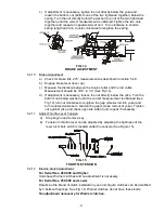
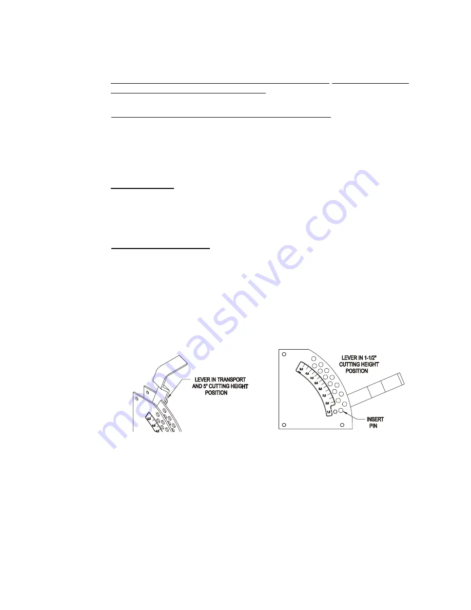
Raise the deck lever to the transport position (also the 5” cutting height
position). See Fig 9.
For Kohler 26 HP EFI units and all 72” units the deck can be raised by
pulling the deck lever up and/or by pushing on the deck lift assist lever.
NOTE: When changing cutting height positions, always come to a
complete stop and disengage the mower blades.
FIG. 9
CUTTING HEIGHT POSITION
d)
Insert height adjustment pin into hole corresponding to desired cutting
height and install hairpin cotter. See decals on the sides of deck lift plate.
e)
Move lever out of transport (or 5” cutting height) position and down onto
height
adjustment
pin
to
mow
at
selected height.
f)
To transport, move lever back up to transport (or 5” cutting height) position.
Note: The foot operated deck lift assist lever (standard on 72” units
the Kohler 26 HP EFI units and optional on all other models) can be
used to momentarily lift the deck to clear objects. Be sure that blades
are disengaged.
Summary of Contents for Laser Z LZ18KC523
Page 1: ......
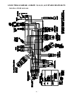
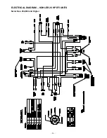
Page 57: ... 52 8 ELECTRICAL DIAGRAM KOHLER 18 22 23 25 HP AIR COOLED UNITS Serial Nos 251 999 and Lower ...
Page 58: ... 53 ELECTRICAL DIAGRAM KOHLER 23 25 HP AIR COOLED UNITS Serial Nos 252 000 and Higher ...
Page 59: ... 54 ELECTRICAL DIAGRAM 22 23 HP KAWASAKI LIQUID COOLED UNITS ...
Page 60: ... 55 ELECTRICAL DIAGRAM KOHLER 26 HP EFI UNITS Serial Nos 251 999 and Lower ...
Page 61: ... 56 ELECTRICAL DIAGRAM KOHLER 26 HP EFI UNITS Serial Nos 252 000 and Higher ...
Page 62: ... 57 ELECTRICAL DIAGRAM 23 HP KAWASAKI AIR COOLED ...
Page 63: ... 58 ELECTRICAL DIAGRAM 27 HP KAWASAKI LIQUID COOLED ...
Page 64: ... 59 9 HYDRAULIC DIAGRAM ...
Page 67: ... 62 NOTES ...
Page 68: ... 63 SERVICE RECORD Date Description of Work Done Service Done By ...
Page 69: ... 64 ...


