Operation
Choke Control
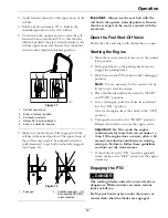
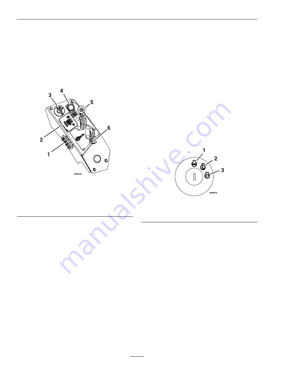
Located on right console (black lever) (see Figure 6).
The choke is used to aid in starting a cold engine.
Moving the choke lever forward will put the choke in
the “ON” position and moving the choke lever to the
rear, to the detent, will put the choke in the “OFF”
position. Do Not run a warm engine with choke in
the “ON” position.
Figure 6
Right Console
1.
Fuses
4.
PTO engagement switch
2.
Message display
5.
Throttle
3.
Ignition switch
6.
Choke
Throttle Control
Located on right console (red lever) (see Figure 6).
The throttle is used to control engine speed. Moving
the throttle lever forward will increase engine speed
and moving the throttle lever to the rear will decrease
engine speed. Moving the throttle forward into the
detent is full throttle.
Brake Lever
Located on right side of unit, just to the front of the
RH motion control lever.
The brake lever engages a parking brake on the drive
wheels.
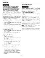
Note:
The LCD indicator appears in the message
display on the RH console when the park brake is
engaged (see Figure 8).
Pull the lever up and rearward to engage the brake.
Push the lever forward and down to disengage the
brake.
The unit must be tied down and brake engaged when
transporting.
Ignition Switch
Located on right console (see Figure 6).
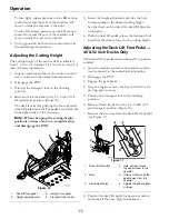
The ignition switch is used to start and stop the
engine. The switch has three positions “OFF”, “ON”
and “START”. Insert key into switch and rotate
clockwise to the “ON” position. Rotate clockwise to
the next position to engage the starter (key must be
held against spring pressure in this position). Allow
the key to return to the “on” position immediately
after the engine starts.
Figure 7
1.
Off
3.
Start
2.
On
Note:
Brake must be engaged, motion control
levers out (neutral lock position) and PTO switch
disengaged to start engine. (It is not necessary for the
operator to be in the seat to start the engine.)
Hour Meter
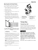
Located on the right console in the message display
(see Figure 6 and Figure 8).
The hour meter records the number of hours that
the engine has run.
20
Summary of Contents for LAZER Z E-SERIES Operators
Page 1: ...LAZER Z E SERIES For Serial Nos 312 000 000 Higher Lazer Z LZE Units Part No 4501 202 Rev A ...
Page 53: ...Schematics Hydraulic Diagram 53 ...
Page 55: ...Notes 55 ...
Page 56: ...Notes 56 ...
Page 57: ...Service Record Date Description of Work Done Service Done By 57 ...
Page 58: ...58 ...


