Operation
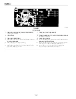
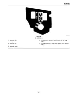
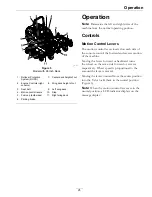
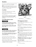
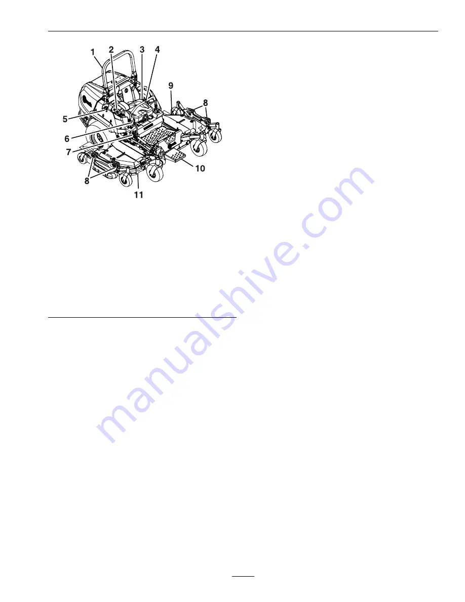
g237956
Figure 5
Model with 96 Inch Deck
1.
Rollover Protection
System (ROPS)
7.
Center deck height of cut
2.
Engine Controls (right
console)
8.
Wing deck height of cut
3.
Seat belt
9.
Left wing deck
4.
Motion control levers
10.
Step
5.
Fuel cap (both sides)
11.
Right wing deck
6.
Parking brake
Operation
Note:
Determine the left and right sides of the
machine from the normal operating position.
Controls
Motion Control Levers
The motion control levers located on each side of
the console control the forward and reverse motion
of the machine.
Moving the levers forward or backward turns
the wheel on the same side forward or reverse
respectively. Wheel speed is proportional to the
amount the lever is moved.
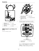
Moving the levers outward from the center position
into the T-slot locks them in the neutral position
(Figure 6).
Note:
When the motion control levers are in the
neutral position, a LCD indicator displays on the
message display.
25

