Operation
B.
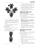
Insert the height adjustment pin into the hole
corresponding to the desired cutting height.
See the decal on the side of the deck lift plate
for cut heights.
6.
Adjust the side wing decks:
A.
Make sure the engine is off, the key has been
removed, and the deck wings are locked in
place.
B.
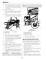
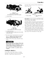
Unlock the cam locks located on the height of
cut channel on the wing deck (see Figure 17).
g239055
Figure 17
1.
Unlock cam lock
3.
Lynch pin
2.
Height of cut pin
C.
Remove the lynch pin from the height of cut
pin on both the front and rear channels.
D.
Move the wing deck to the appropriate height
and reinstall the height of cut pins and lynch
pins as shown in Figure 17.
E.
Lock the cam lock.
F.
Repeat for other wing deck.
7.
If additional height of cut range is desired, adjust
the front and rear gauge wheels on the wing deck:
A.
Remove the mounting hardware from the
gauge wheel.
B.
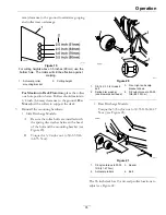
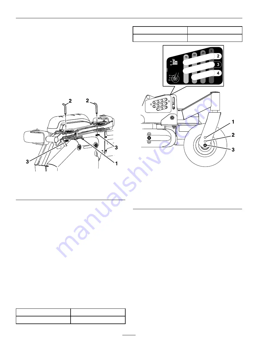
Adjust the front and rear gauge wheels to the
appropriate hole location (see the chart below
and Figure 18) and reinstall the mounting
hardware.
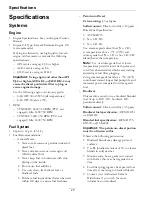
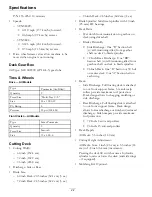
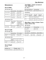
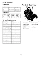
Hole Location
Height of Cut Range
Top hole (-1 on decal)
1–3.5 inches (25–89 mm)
Middle hole (0 on decal)
2–4.5 inches (51–114 mm)
Bottom hole (+1 on decal) 3–5.5 inches (76–140 mm)
g212253
Figure 18
Height of Cut Range
1.
Top hole (-1 on decal)
2.
Middle hole (0 on decal)
3.
Bottom hole (+1 on decal)
C.
Repeat for other wing deck.
Adjusting the Anti-Scalp Rollers
It is recommended to change the anti-scalp roller
position when the height of cut has changed.
1.
Stop the machine and move the motion control
levers outward to the neutral locked position.
2.
Disengage the PTO.
3.
Engage the park brake.
4.
Stop the engine, remove the key and wait for all
moving parts to stop.
5.
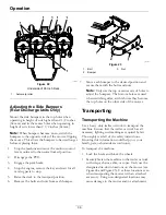
After adjusting the height of cut, adjust the
anti-scalp rollers by removing the mounting
hardware.
6.
Place the rollers in one of the positions shown
(Figure 19). Rollers will maintain 3/4 inch (19
34

