Maintenance
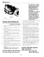
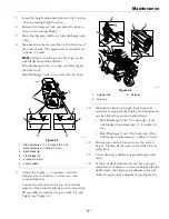
g228555
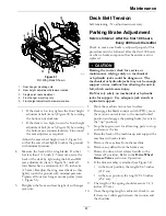
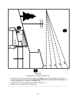
Figure 52
1.
Front location
5.
Spring
2.
Rear location
6.
Link assembly
3.
3 1/4 inches (8.3 cm)
7.
Length
4.
Gap
11.
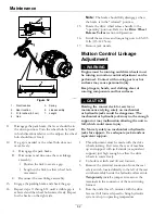
Disengage the park brake, the lever should be in
the down position. Turn the wheel hub by hand
in both directions relative to the caliper; the wheel
hub should move freely.
12.
If a gap is needed or the wheel hub does not
move freely:
A.
Disengage the park brake.
B.
Disconnect and fine-tune the rear linkage
assembly:
•
Shorten the link to create a gap.
•
Lengthen the link to allow wheel hub
movement.
C.
Reconnect the rear linkage assembly.
13.
Engage the parking brake and check the gap.
14.
Repeat steps 11 through 14 until a visible gap is
achieved and the wheel hub rotates freely. Repeat
for the brake on the right side.
Note:
The brake should fully disengage when
the brake is in the “released” position.
15.
Rotate the drive wheel release handle to the
“operating” position. Refer to the
Drive Wheel
Release Valves
section in Operation.
16.
Install the rear tires and torque lug nuts to 85-105
ft-lb (115-142 N-m).
17.
Remove jack stands.
Motion Control Linkage
Adjustment
WARNING
Engine must be running and drive wheels must
be turning so motion control adjustment can be
performed. Contact with moving parts or hot
surfaces may cause personal injury.
Keep fingers, hands, and clothing clear of
rotating components and hot surfaces.
CAUTION
Raising the mower deck for service or
maintenance relying solely on mechanical
or hydraulic jacks could be dangerous. The
mechanical or hydraulic jacks may not be enough
support or may malfunction allowing the unit to
fall, which could cause injury.
Do Not rely solely on mechanical or hydraulic
jacks for support. Use adequate jack stands or
equivalent support.
1.
This adjustment must be made with the drive
wheels turning. First raise the rear of machine
up and support with jack stands (or equivalent
support) just high enough to allow the drive
wheels to rotate freely.
2.
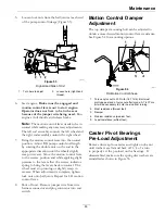
Unhook seat latch and tilt seat forward.
3.
Remove the electrical connection from the seat
safety switch, located directly to the left of the seat
switch assembly beside the hydraulic oil reservoir.
Temporarily
install a jumper wire across the
terminals in the connector of the main wiring
harness.
4.
Run the unit at least 5 minutes with the drive
levers at full forward speed to bring hydraulic
system oil up to operating temperature.
62

